


30
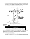
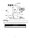
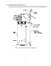
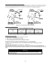
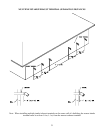
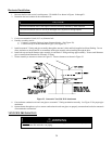
Through The Wall Venting With Low Ground Clearance:
When venting cannot exit through the wall at a height greater than or equal to 12 inches (30.5 cm) (and above expected snow
level) from the ground, then the installation must be modified as shown below (see Figure 18). Refer to Tables 3 or 4 for
maximum venting lengths using 2 inch (5.1 cm), 3 inch (7.6 cm) or 4 inch (10.2 cm) diameter plastic pipe.
Figure 18. Vent Terminal (Low Ground Clearance)
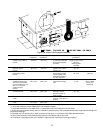
Maximum Vent Length Determination
Power Vent Maximum Vent Length
Model
Number
Max Vent Length in feet
(meters) for 2 inch
(5.1 cm) PVC, CPVC,
or ABS
Max Vent Length in feet
(meters) for 3 inch
(7.6 cm) PVC, CPVC,
or ABS
Max Vent Length in
feet (meters) for 4 inch
(10.2 cm) PVC, CPVC,
or ABS
EFR60T120, EF100T150 60 (18) 120 (36) 170 (51)
Table 4
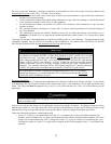
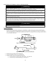
Determining required vent length:
1. Determine the total length of straight vent pipe (in feet) required.
2. Add 5 feet (1.5 m) of venting for every 90° elbow.
3. Add 2 ½ feet (.7 m) of venting for every 45° elbow.
4. Total vent length cannot exceed “Max. Vent Length” in Table 4.
Example of Total Vent Length for EF100T199 with a power vented installation:
A 3 inch (7.6 cm) venting system has a total of six 90-degree elbows and a total straight pipe length of
55 feet (16.5 m).
Equivalent vent length for elbows: 6 x 5 feet (1.5 m) = 30 feet (9 m).
Total equivalent vent distance = 55 feet (16.5 m) + 30 feet (9 m)
= 85 feet (25.5 m) total equivalent vent
length. This is below the maximum allowed distance of 100 feet (30 m) for this model using 3 inch (7.6 cm)
vent.
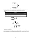
NOTICE
Do not include the 3 inch (7.6 cm) condensate elbow or vent terminals in determining
maximum vent length.