


Ultra High Efficiency Water Heaters
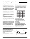
NOTE:Diagrams are for both the 60 and 100 gallon models.
3
⁄4" NPTGas Inlet
1
1
⁄2" NPT
Outlet
1
" NPT Space
H
eating Outlet
1" NPT Space
Heating Return
1
1
⁄2" NPTInlet
3" PVC Exhaust
3" PVC Air Inlet
G
E
B
D
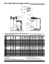
3" PVC
EXHAUST
1
⁄2" NPTCONDENSATE
CONNECTION
2
3
⁄8"
F
A
C
H
T & P Valve
Cleanout
Drain
8
1
⁄4
B
2
8
1
⁄4
Gas Inlet
T & P Valve
8
1
⁄4
E
xhaust
Air Intake
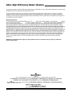
NATURAL GAS AND LIQUID PROPANE GAS
eF Series
®
Commercial Ultra High Efficiency Water Heater
Meet or exceed ASHRAE 90.1b (current standard) C.E.C. Listed
Includes Installed T&P Valve and Electronic Ignition
Model
Number
F
Floor to
Vent
Outlet
in.
Approx.
Shipping
Weight
lbs.
E
Floor to
Gas
Conn.
in.
A
Floor to
Top of
Heater
in.
Input
BTU
1
ST
Hour
Delivery
at 100°F
Rise
Gal.
Stg.
Capacity
U.S.
Gal.
Therm.
Eff.
%
D
Cold
In
in.
C
HW
Out
in.
B
Jacket
Dia.
in.
140°F100°F40°F
Recovery GPH
at Degree Rise
EF-60T-125E-3N(A)
EF-60T-150E-3N(A)
EF-60T-199E-3N(A)
EF-100T-150E-3N(A)
EF-100T-199E-3N(A)
EF-100T-250E-3N(A)
EF-100T-300E-3N(A)
EF-100T-399E-3N(A)
125,000
150,000
199,999
150,000
199,999
250,000
300,000
399,999
★
★
★
★
★
★
★
★
●
●
●
●
●
●
●
●
187
211
265
250
309
364
405
521
V
V
V
V
V
V
V
V
364
423
558
450
597
735
836
1127
145
169
223
180
239
294
335
451
104
121
159
129
171
210
239
322
60
60
60
100
100
100
100
100
96.0
93.0
92.0
99.1
98.5
97.0
92.0
93.0
57
57
57
77
5
/8
77
5
/8
77
5
/8
77
5
/8
77
5
/8
42
42
42
63
63
63
63
63
570
570
570
900
900
900
900
950
28
1
/4
28
1
/4
28
1
/4
28
1
/4
28
1
/4
28
1
/4
28
1
/4
28
1
/4
5
5
5
5
5
5
5
5
1
1
/2
1
1
/2
1
1
/2
1
1
/2
1
1
/2
1
1
/2
1
1
/2
1
1
/2
3
/4
3
/4
3
/4
3
/4
3
/4
3
/4
3
/4
1
3
/4
3
/4
3
/4
3
/4
3
/4
1
1
1
13
13
13
13
13
13
13
13
53
1
/2
53
1
/2
53
1
/2
74
3
/4
74
3
/4
74
3
/4
74
3
/4
73
1
/4
52
1
/2
52
1
/2
52
1
/2
73
1
/8
73
1
/8
73
1
/8
73
1
/8
73
1
/8
40
40
40
60
60
60
60
60
G
Floor to
Air
Intake
in.
H
Floor to
T&P
Conn.
in.
Gas
Conn.
Dia.
in.
Water
Conn.
Dia.
in.
Relief
Valve
Open
in.
Model
Number
F
Floor to
Vent
Outlet
mm.
Approx.
Shipping
Weight
kgs.
E
Floor to
Gas
Conn.
mm.
A
Floor to
Top of
Heater
mm.
Input
kW
1
ST
Hour
Delivery
at 56°C
Rise
Liters
Stg.
Capacity
Liters
Therm.
Eff.
%
D
Cold
In
mm.
C
HW
Out
mm.
B
Jacket
Dia.
mm.
78°C56°C22°C
Recovery LPH
at Degree Rise
EF-60T-125E-3N(A)
EF-60T-150E-3N(A)
EF-60T-199E-3N(A)
EF-100T-150E-3N(A)
EF-100T-199E-3N(A)
EF-100T-250E-3N(A)
EF-100T-300E-3N(A)
EF-100T-399E-3N(A)
36.6
43.9
58.6
43.9
58.6
73.2
87.9
117.2
★
★
★
★
★
★
★
★
●
●
●
●
●
●
●
●
708
799
1003
946
1170
1378
1533
1972
V
V
V
V
V
V
V
V
1378
1601
3112
1703
2260
2782
3165
4266
545
640
844
681
905
1113
1268
1707
394
458
602
488
647
795
905
1219
227
227
227
379
379
379
379
379
96.0
93.0
92.0
99.1
98.5
97.0
92.0
93.0
1448
1448
1448
1972
1972
1972
1972
1972
1067
1067
1067
1600
1600
1600
1600
1600
259
259
259
408
408
408
408
431
718
718
718
718
718
718
718
718
128
128
128
128
128
128
128
128
38
38
38
38
38
38
38
38
19
19
19
19
19
19
19
25
19
19
19
19
19
25
25
25
330
330
330
330
330
330
330
330
1359
1359
1359
1899
1899
1899
1899
1861
1324
1324
1324
1857
1857
1857
1857
1857
994
994
994
1527
1527
1527
1527
1524
G
Floor to
Air
Intake
mm.
H
Floor to
T&P
Conn.
mm.
Gas
Conn.
Dia.
mm.
Water
Conn.
Dia.
mm.
Relief
Valve
Open
mm.
For pr
opane gas models change suf
fix “N” to “X” and r
emove “E” fr
om the model number.
Example: EF-100T-150-3X
V - 115V A.C. Required
•
- Electr
onic Ignition
★- Listed with California Energy Commission
(A) ASME - All models are available with ASME construction. To order ASME
construction add the (A) to the end of the model number. Example: EF-60T-125E-3NA
Note:
The weight is the same for both ASME and Non-ASME models.
NSF Construction Available with optional kit
Complies with SCAQMD low NOx requirements — 10.39 ng/joule
Design certified by CSA International (formerly AGA/CGA)
Amp Draw range = 1.0 to 1.8 amps and 7.0 amps for EF-100T-399
150 PSI Working Pressure (1034 kPa), 300 PSI Test Pressure (2068 kPa)