


22
Installation (Vent-Air Intake System Installation) continued-
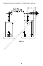
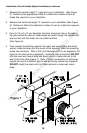
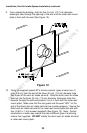
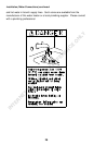
9. From outside the building, slide the five (5) inch (12.7 cm) diameter
telescopic tube through the opening in the wall until the outer wall mount
plate is flush with the wall (See Figure 12).
Figure 12
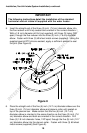
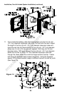
10. Using the supplied special RTV silicone sealant, apply a bead one (1)
inch (2.5 cm) from the end of the three (3) inch (7.6 cm) diameter tube
that is part of the vent-air intake terminal. Slide the direct vent-air intake
terminal into the three (3) inch (7.6 cm) diameter telescopic tube that
extends through the wall and position it so it is flush with the outer wall
mount plate. Make sure that the rain guard and the word “HOT” on the
end of the direct vent-air intake terminal are oriented properly. Secure the
direct vent-air intake terminal to the outer wall mount plate and wall with
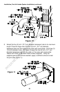
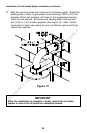
four (4) #10 x 1 inch screws (supplied) (See Figure 13). Note: Certain
construction of walls may require the use of different type of anchoring
means than supplied. DO NOT modify the direct vent-air intake terminal
or outer wall mount plate.
INTERNET VERSION FOR REFERENCE ONLY