


SERVICE PROCEDURE D24-II
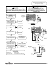
Pilot Operation Testing
CAUTION
Be Careful When Making Voltage
Measurements or Jumping Terminals
Not to Damage or Deform Connectors or
Connector Pins.
DANGER
120 volt exposure. To avoid personal injury,
use caution while performing this procedure.
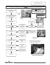
Condition:
Pilot lights, no flame signal.
Module continues to spark until
system “Lock Out”.
Main burner will not light.
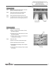
Disconnect white flame sense
lead from ignition module at the
“SENSE” location. Set multi-
meter to the “Micro Amps”
setting (
ȝA) (see note). Check
micro amp reading. Be sure
module is sparking during this
test.
(see illustration 2)
Micro-amp readings
0.000 Micro Amp = Replace module.
1.0 micro amp or less = Clean pilot flame rod or replace pilot.
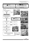
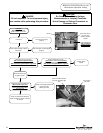
C
heck for loose or damaged
g
round wire(s). Are ground wires
okay?
Check for loose or damaged
flame sense lead from pilot to
module. (see illustration 1).
Is flame sense lead okay?
Repair wire lead
or replace pilot.
White flame
sense lead from
pilot
Illustration 1
White wire lead
from pilot
Illustration 2
Meter
Probe
Meter
Probe
Repair ground
wire(s) or replace
as needed.
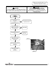
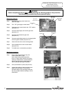
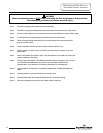
NOTE:
If multi meter is not capable of
testing micro amps, check
continuity of sense lead. If no
continuity, clean pilot flame rod
or replace pilot.
(see illustration 3)
Illustration 3
Flame rod
Flame rod
Flame rod
Y
Y
N
N
Multi-meter set
to micro-amp
setting (
ȝA)
Meter
Probe
Meter
Probe
Multi-meter set
to check
continuity.
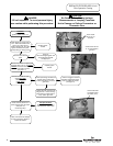
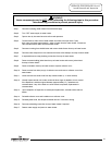
Check venting conditions or
negative pressure
Is vent system okay?
Correct improper
venting condition.
N
Is heater condensing causing
pilot interruption?
Determine cause for
condensing and correct.
Under sized heater or high
demand periods
Y
Y
N
Page 9
9