


S
EQUENCE OF OPERATION
MII Series Commercial Electric Water Heaters can use either immersion thermostat (contactor models) or
surface mounted thermostats. Sequence of operation for each configuration is explained below. It would be impractical
to show all wire diagrams applicable to both configurations. A “typical wiring diagram” is illustrated to aid in
understanding the principles of the operating sequence.
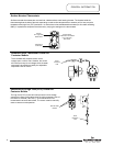
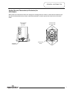
Immersion Thermostat (Contactor Models): Configured to use a single immersion thermostat to control one or more
contactors to energize or de-energize all elements simultaneously. In addition, a separate high limit (ECO) control with
manual reset is wired in series with the thermostat. Both controls use a direct immersion bulb inserted into the tank to
sense water temperature. Immersion thermostat and high limit control are mounted to provide temperature adjustment
and manual reset access from the exterior of the unit.
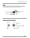
Surface Mounted Thermostats: Surface mounted thermostats are mounted inside the lower control box, in a bracket
above each heating element. The bracket holds the thermostat against the side of the tank responding to tank surface
temperatures to sense a call for heat, set point temperature and high limit (ECO) activation. As each element is controlled
by a dedicated thermostat, it is possible to sequence the elements by varying the settings on the thermostat. However,
600V models w/ surface mounted thermostats operate contactors in the same manner as an immersion thermostat
model, only using surface thermostats to sense the call for heat.
Sequence of operation for each system is explained below.
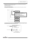
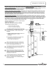
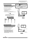
Sequence of Operation:
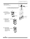
Immersion Thermostat (Contactor Models).
Line voltage is applied across terminals of fuse block
or a terminal block. Line voltage continues down and
connects to terminals L1, L2 & L3 of one or more
contactors.
A) Contactor is open (no call for heat), so there is no
voltage across terminal T1, T2 & T3
of contactor.
B) The contactor is controlled by the control circuit
consisting of the immersion thermostat,
ECO (hi limit) and contactor coil.
Page 10
1
2
OR
Terminal Block
F
use Block
L
ine Voltage
Contactor
Contactor
Coil
ECO
(High Limit)
T’stat
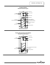
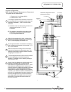
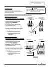
When the thermostat calls for heat, contacts close
inside the thermostat completing the circuit through
the ECO and energizing the contactor coil.
The system has two distinct circuits.
1. Power circuit (shown solid line).
2. Control Circuit (shown dotted line).
The energized contactor coil causes the contactor to
close energizing the elements from terminals T1, T2
& T3 of the contactor.
3
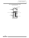
When the temperature setting of the thermostat is
reached, the contacts in the thermostat open. This
interrupts current flow through the control circuit de-
energizing the contactor coil.
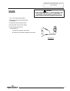
4
The de-energized contactor coil causes the contactor
to open, interrupting current flow through the
elements. The heater is now in stand-by waiting for
the next call for heat.
5
Heating Elements
10