


BRADFORD WHITE CORP.
Page 30
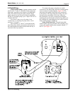
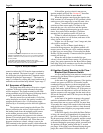
control switches this 24V from the input terminal to
the stage terminal. The input for stage 1 is initiated
by closing the circuit between the 2 terminals on the
terminal strip labeled "input stage 1." The input for
stage 2 is initiated by closing the circuit between the 2
terminals on the terminal strip labeled "input stage 2."
6.4 Sequence of Operation
The pump time delay relay will receive a signal
to initiate. If the unit is pump-mounted, the pump
will be energized. The pump terminals on the eld-
wiring terminals strip will energize a eld pump that is
properly interlocked with the Brute Deluxe.
Once the water ow switch makes, if all of the
safety interlocks are closed, the ignition module will
energize the blower(s) for a 15-second pre-purge,
followed by a 40-second period to allow the ignitor to
heat.
The ignition control energizes the blower. The
blower pressurizes the air box (which supplies air to
the burners) and closes the normally-open contact
on the airow pressure switch. The blocked vent
pressure switch senses the pressure in the exhaust
plenum. This switch opens if the pressure is excessive
(as an indicator of a blocked vent). When these two
pressure switches are closed, voltage is sent to the
PSW terminal on the ignition control, which allows the
ignition module to proceed with the ignition sequence.
If the airow proving circuit is not proven,
ignition module will lock out. Section 6.5 describes
the result of air ow faults in more detail.
When the ignition control gets the signal at the
PSW terminal, it will energize its MV terminal, which
sends power to the stage one (or on/off) main valve.
After a 7-second trial for ignition, the ignitor
switches to ame sense mode. If a ame is not
detected, the gas valve will close and the ignition
module will attempt ignition again (up to two more
times, for a total of three attempts.) If all three
attempts fail, the ignition control will lock out.
If ame is sensed, the burner will continue to
re as long as there is a call for heat, and none of the
safety circuit is interrupted.
If there is a call for stage 2 on a 2-stage unit, that
valve will be energized.
If there is a loss of ame signal during a
successful ring sequence, the ignition control will
remove power from the gas valves, and then attempt
to light up to two more times. If successful, the Brute
Deluxe will re normally. If unsuccessful, the ignition
control will lock out.
When the call for heat is satised, the gas
valve(s) closes, and the blower starts a 45 second post-
purge. Any pump connected to the Brute Deluxe pump
time delay relay will continue to run for the time delay
period (dialed by the user, 0.1 to 10 minutes).
6.5 Ignition Control Reaction to Air Flow /
Blocked Vent Pressure Switch
Air ow and blocked vent status are continuously
monitored by the Brute Deluxe ignition control, at the
control’s PSW terminal.
At the start of an ignition sequence, if the ignition
control sees power at PSW for 30 seconds, but the
combustion blower has not yet been energized by the
control (F1 and F2). The ignition control will remain
in this fault mode, with the blower off. If the power to
PSW is removed while there is still a call for heat, the
ignition sequence will start again, but the main valves
will not be energized until PSW sees power during the
ignition sequence.
At the start of an ignition sequence, the control
sends the combustion blower output (F1 and F2). If
the control does not see power at PSW for more than
30 seconds, the control will remain in this fault mode,
with the blower on. If proper airow is later detected
on PSW, the control begins a pre-purge and a normal
trial for ignition.
If the PSW signal is lost while the Brute Deluxe
is ring, the control will immediately de-energize the
gas valve terminal (MV). The blower will remain on
for the post-purge period (45 seconds), and the control
will continue to monitor the PSW input. If the signal
is detected during the post-purge period, a normal trial
for ignition will begin, starting with the 15-second
pre-purge. If the signal is not detected during the post-
purge, the control will lockout with the blower off.
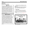
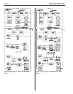
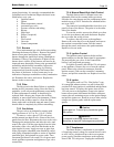
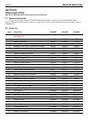
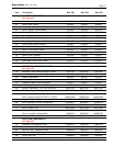
*1 Difference between the temperatures at which the two switches
make R-W. Adjustable from 3°F to 10°F (1.7°C to 5.6°C) on standard
models, or from 3.6°F to 12°F (2.0°C to 6.7°C); 55°F to 175°F (13°C
to 79°C) models.
*2 Two DPDT switches operate in sequence. Each switch
differential is fixed at approximately 3°F (1.7°C) on standard models,
or 3.6°F (2.0°C); 55°F to 175°F (13°C to 79°C) models.
Figure 19. Honeywell L8008G.