


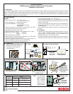

3.7 Set the PIR Sensitivity. 3.9 Mount the Detector Base.
3.10 Remove the battery
tab, install the wall
tamper spring,
replace the
cover and
base.
During the warm-up period, the tricolor LED will flash red until the unit has stabilized
(approximately 5 minutes). When the LED stops flashing, the detector is ready to be
walk tested.
If the Wall Tamper is desired, gently
press the Spring onto the tapered
shaft. Do not force it down onto the
shaft. As you place the unit onto its
base, be sure the spring extends
through the knockout to the wall.
3.11 Walk test the detector. Perform this test at the time of installation and monthly thereafter. To ensure continual daily operation,
the end user should be instructed to walk through the far end of the coverage pattern. This ensures an alarm output prior to
arming the system.
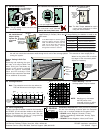
4.0 Coverage Patterns
Note: The protective zone is the area where the
PIR and Microwave technologies overlap.
NOTE: Masking only eliminates
the PIR portion of the
coverage and has no effect
on the Microwave pattern.
5.0 Panel Programming
There is a two-part ID sticker located on the housing of
the RF835E. You will need the number on this sticker to
program the Detector into the control panel. See your
panel's Programming Guide for programming
information on wireless type devices.
167770187
167770187
ID Number
3.8 Uncover the Look Down Lens.
INT
STD
- 6
- 10
MW
MIN
MAX
PIR
Sensitivity
Selection Pins
For pet applications,
set jumper to STD.
INT
STD
INT
STD
INT
STD
Note: The INT setting is more sensitive than
the STD setting.
Note: The Wall Tamper cannot be used in
corner mount installations or when
using the swivel bracket.
Feet
0 5 10 15 20 25 30 35
0
5
10
15
20
5
10
15
20
0
Meters
1.6 3.2 4.8 6.4 8 9.6 11.2
TOP VIEW
B
C
D
E
H
I
J
K
N
O
P
Q
R
S
T
U
W
X
LZ
F
G
L
Z
0
3
3
6
6
Surface
mount
Corner mount
Corner mount
Breakaway
Thinwall
to activate
Wall
Tamper
Switch
INT
STD
- 6
- 10
MW
MIN
MAX
Peel away
the mask
In non-pet applications only, if
look-down is desired, peel away
the look-down mask. Do not
remove the clear plastic lens.
Pattern Masking: The PIR
coverage pattern may be masked.
Pattern Testing in Walk Test
Mode
Removing and replacing the cover
will start a 90 second Walk Test
Mode. During this Test Mode, any
activity in the sensor’s coverage
pattern will cause a transmitted
alarm and LED activation. Each
alarm will also extend the Test Mode
for an additional 90 seconds.
Green =
PIR detect
Yellow =
MW detect
Red =
Alarm
10
0
Feet
0 5 10 15 20
25
30
-5°
SIDE VIEW
0
Meters
1.6 3.2 4.8 6.4 8 9.6
35
B-L
N-QR-U,ZW-XLZ
11.2
0
3
Remove
masking for
Look-Down
Zone
Watch for the yellow LED to indicate
the edges of the microwave pattern.
Adjust as necessary.
noitidnoCDEL esuaC
deRydaetSmralAtinU
wolleYydaetS)tseTklaW(noitavitcAevaworciM
neerGydaetS)tseTklaW(noitavitcARIP
deRgnihsalFpU-rewoPretfAdoirePpU-mraW
-ruof(deRgnihsalF
)ecneuqesdeslup
tinUecalpeReruliaFRIProevaworciM
BCDEFGH I JKL
NR
W
SOZPTXUQ
RF835E Lens
(inside view)
INT
STD
MIN
MAX
MIN
MAX
Set the adjustment
as low as possible
for proper catch
performance
Countries of Intended Use: These products are intended
for use in the following countries within the European
Union and in countries outside the European Union:
• RF835E Austria, Belgium, Denmark, Finland,
Greece, Luxembourg, Netherlands, Norway, Spain,
and Sweden.
• RF835E-C United Kingdom, Ireland, and France.
ID Label
Pull battery
tab out from
between the
battery and
its contact.
© 2004 Bosch Security Systems
130 Perinton Parkway, Fairport, New York, USA 14450-9199
Customer Service: (800) 289-0096; Technical Support: (888) 886-6189
03/04
RF835E Installation Instructions
P/N: 48544D Page 2