


Page
2 of 3
BOSCH SECURITY SYSTEMS
Do not manually back drive the pan or tilt axis by hand. Back driving may strip teeth off the internal gears
and in so doing will void the warranty.
M8 Stainless steel nuts, bolts and washers should be used to secure the base to the mounting surface. Suitable
sealant or a gasket should be used between the camera base and the mounting surface.
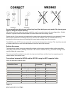
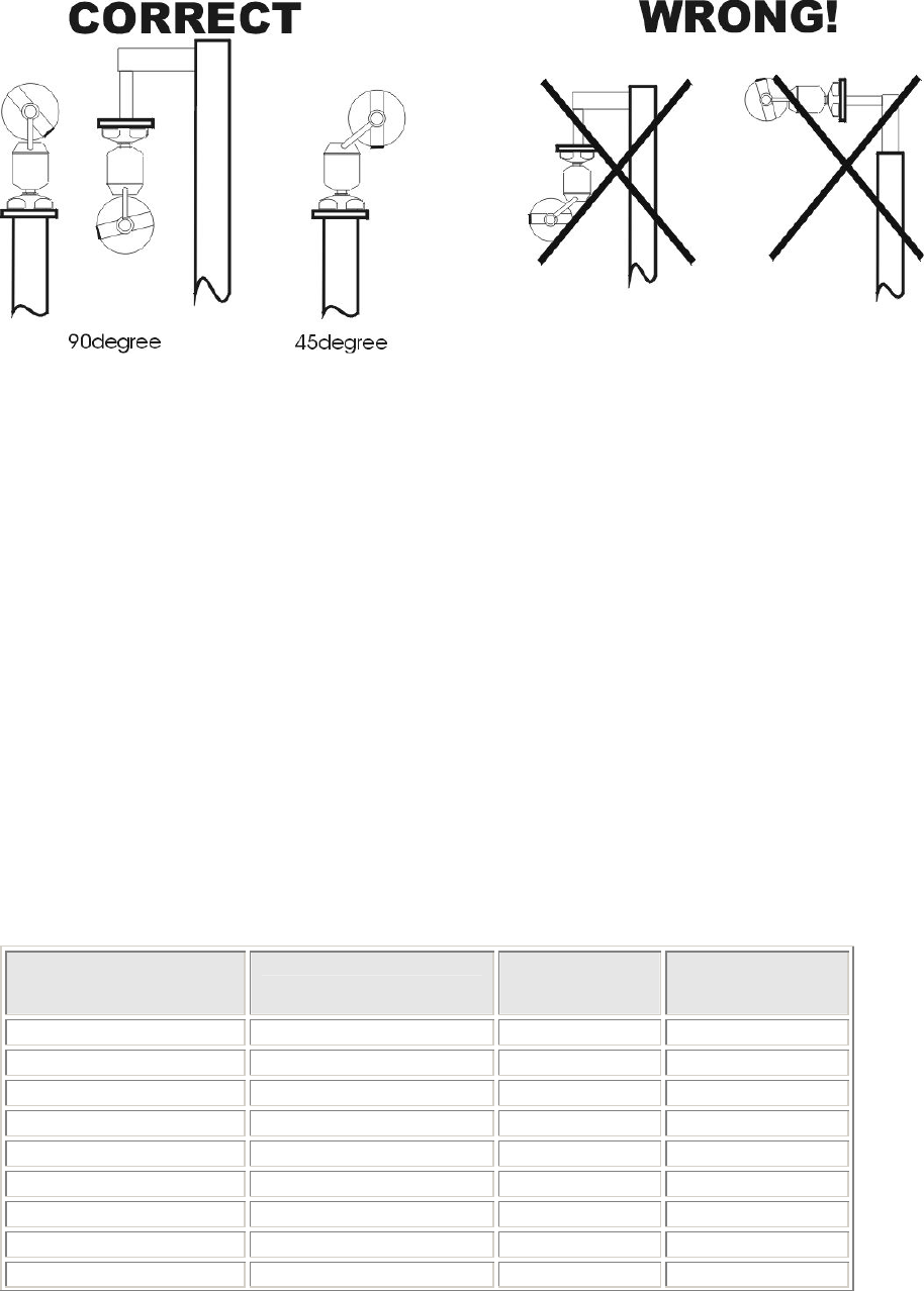
Ensure that the 12 pin connector is located into the camera base plug and that the lock ring is tightened. Ensure
that the base compartment containing the 12 way connector is moisture proof. On inverted units it is very
important that the connector area is water tight to prevent water pooling around the connector.
The MiC400 series of PTZ cameras comes with a security attachment point as standard. This should be attached
to a safety chain which in turn should be attached to a secure part of the structure.
Earthing the camera
The camera and camera housing are electrically isolated so the housing should be safety earthed regardless.
This safety earth should be a bonding connection to the camera’s outside case. E.g. one of the securing screws
used for bolting the camera down.
The camera should be earthed at one point only to prevent earth loops and thus hum bars appearing on the
camera picture in the control room.
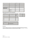
Connections between the MIC400 and the MIC-PSU using the MIC Composite Cable:
Note: all connections must be made
MIC400 Composite
Cable Wire Colour
Function PSU Terminal
Connector
PSU Terminal ID
marking
Red 15v AC supply HD3-1 Power
Green 15v AC supply return HD3-2 Power
White Camera Rx B HD3-3 RxB
Yellow Camera Rx A HD3-4 RxA
Drain Wire Gnd HD3-5 GND
Blue Camera Tx A HD3-6 TxA
Violet Camera Tx B HD3-7 TxB
Coax Core Video HD3-8 Video
Coax Screen Video Return HD3-9 Vid 0v