


Page
3 of 3
BOSCH SECURITY SYSTEMS
Black Tamper Switch HD3-10 Tamp Sw
Orange Wash HD3-11 Wash
Grey 0v Tamper Switch. HD6-1
Brown 0v Wash HD6-2
IR lamp, Heater or
Speaker Option
Grey IR Lamp + or Speaker +
or Heater +
HD6-1 IR +
Brown IR Lamp- or Speaker -
or Heater -
HD6-2 IR -
External Connections to the Power Supply Unit
Please Note:
Cameras are supplied set to address 1, to change the address and configure the camera you will require the
Universal CamSet program and a PC with a serial port and an RS232 to RS485/RS422 adaptor. A PC without a
serial port can use the MIC-USB485 CVTR to connect to the MIC-PSU instead.
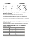
TELEMETRY
Signal Function Telemetry Signal Name HD4 or
HD5
RS485 + to camera RXB Pin 1
RS485 – to camera RXA Pin 2
0v from control room. GND Pin 3
RS485 – to control
room.
TXA Pin 4
RS485 + to control
room.
TXB Pin 5
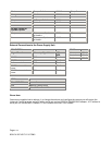
MAINS
Live HD1-1
Neutral HD1-2
Earth HD1-3
VIDEO
Video BNC CN1 Connection
Core Video to Control Room
Screen Video GND to Control Room