


6
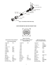
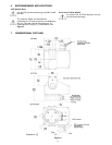
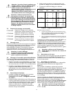
Screws (2)
Strain Relief Clamp
Strain Relief Slot
Shield
Washer
Wire Bundle
Sleeve
Contact
Extender
Connector
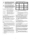
Strip Length
.156 – .015
Figure 1: Shield/Strain Relief Assembly
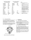
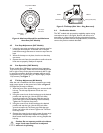
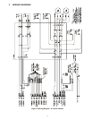
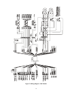
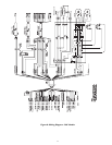
WIRE DESIGNATION AND PIN CONNECTIONS
Figure 2: Pin Outs
345° Non-Pre-Position Models
5,6
Feed –through Wiring
Pin Number Color
1: NC
1
2: NC
1
3: NC
1
4: NC
1
5: Lens Common Green
2
6: Zoom Blue
2
7: Focus Violet
2
8: Unused Brown
2
9: Unused Black
2
10. Accessory White
2,3
11. Accessory Red
2,3
12. Accessory Yellow
2,3
13: NC
1
14: NC
1
15: NC
1
16: Pan Left White
17: NC
1
18: Pan Right Violet
19: P/T Common Blue
20: Tilt Up Brown
21: Tilt Down White/Yellow
22: Ground Green/Yellow
2
23: Camera AC-Line Black
2,4
24: Camera AC-Neutral White
2,4
345° Non-Pre-Position Models
5,6
Standard Wiring
Pin Number Color
1: NC
1
2: NC
1
3: NC
1
4: NC
1
5: NC
1
6: NC
1
7: NC
1
8: NC
1
9: NC
1
10. NC
1
11. NC
1
12. NC
1
13: NC
1
14: NC
1
15: NC
1
16: Pan Left White
17: NC
1
18: Pan Right Violet
19: P/T Common Blue
20: Tilt Up Brown
21: Tilt Down White/Yellow
22: Ground Green/Yellow
2
23: NC
1
24: NC
1
360° Pre-Position and
Non-Pre-Position Models
7,8
Pin Number Color
1: Pan +5V Orange
8
2: Pan Sense (3) Wht/Blk/Yel
8
3: Pan-5V Wht/Blk/Red
8
4: Tilt Sense Wht/Blk/Brn
8
5: Lens Common Green
2
6: Zoom Blue
2
7: Focus Violet
2
8: NC
1
9: NC
1
10. Accessory White
2,3
11. Accessory Red
2,3
12. Accessory Yellow
2,3
13: NC
1
14: NC
1
15: Pan Sense (2) White/Orange
8
16: Pan Left White
17: NC
1
18: Pan Right Violet
19: P/T Common Blue
20: Tilt Up Brown
21: Tilt Down White/Yellow
22: Ground Green/Yellow
2
23: Camera AC-Line Black
2,4
24: Camera AC-Neutral White
2,4