


EN
|
8
Bosch Security Systems | December 13, 2007
LTC 8540/00 Series | Instruction Manual | Installation
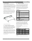
4.2.2 Desk Top Mount
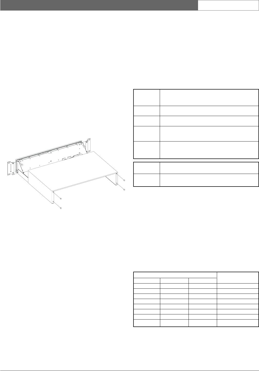
If the unit is not going to be rack mounted, the
enclosure’s mounting ears should be removed. The
cover of the unit must be removed before access to the
mounting ears is possible. Removal of the cover should
only be performed by qualified service personnel. The
unit should always be disconnected from the Allegiant
CPU bay (or alternate power source if one is being
used) before removing the cover.
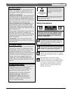
The top cover is fastened to the case by 4 screws
located on the rear of the unit. Once the screws have
been removed, the cover slides back and off the unit.
Remove each mounting ear by removing the screw
holding the mounting ear to the enclosure chassis.
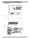
Refer to the drawing below if needed.
Cover and Rack Ears Removal
4.3 Allegiant CPU Bay Connections
With the power turned “OFF” on the Allegiant series
main CPU bay, install the alarm interface unit in the
rack close enough to the location of the main CPU
bay to allow the supplied cable to be used.
Connect one end of the supplied 9-pin D-type cable
labeled “ALARM” to the rear of the unit and the other
end to the Allegiant main CPU bay connector marked
“ALARM”. Remember to tighten both connector
attachment screws at each connection point. The front
panel LED should light upon application of power to
the main CPU bay.
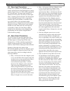
4.4 Operational Settings
The unit contains internal DIP switches which can be
used to set certain operating characteristics. The lid to
the unit must be removed as described above if the
DIP switches need to be changed from their Factory
default settings. Refer to the LTC 8540/00 table below
for DIP locations. The following tables summarize the
DIP switch settings and their associated features:
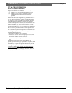
LTC 8540/00
1
Denotes Factory default settings.
The unit communicates with the Allegiant main CPU
bay using RS-232. The first three switches of DIP
switch S101 are used to select the desired baud rate.
Refer to the LTC 8540/00 layout diagram below for
locations. Follow the table if a change from the Factory
default setting is required.
Note that the Allegiant CPU bay must also be set to
the same baud rate.
LTC 8540/00
1
Denotes Factory default settings on units starting with serial
No. 1500.
2
Denotes Factory default settings on units below serial No. 1500.
S929A39AE
S101 - DIP
Switch No. Function
4 ON for RTS/CTS enabled.
OFF to disable RTS/CTS.
1
S103 - DIP Function
Switch No.
1 ON for alarms 1 to 32 as normally open (NO).
1
OFF for alarms 1 to 32 as normally closed (NC).
2 ON for alarms 33 to 64 as normally open (NO).
1
OFF for alarms 33 to 64 as normally closed (NC).
3 ON for alarm output relays as normally open (NO).
1
OFF for alarm output relays as normally closed
(NC).
4 ON for audible buzzer enabled.
1
OFF to disable audible buzzer.
S101 - DIP Switch No. Baud
1 2 3 Rate
OFF OFF OFF 19200
1
OFF OFF ON 9600
OFF ON OFF 4800
OFFONON2400
ON OFF OFF 1200
2
ON OFF ON 600
ON ON OFF Not Used
ON ON ON Not Used