


LTC 4600 Series | Instruction Manual | Installation
Bosch Security Systems | July 08, 2008
EN
|
14
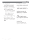
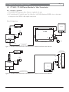
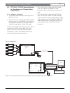
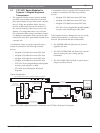
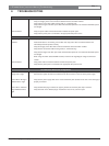
4.7 LTC 4671 Series Modules for
System4 / Allegiant Keyboard
Transmission
1. The supplied 120 ohm resistor must be installed
across the external data connections when these
fiber optic modules are used with certain controller
devices. Follow the guidelines below, however,
because of differences between the hardware of
new and old controller units, these cases are not
absolute. If a configuration does not work when
first connected without using a termination resistor,
try adding the termination resistor across the data
connections of the fiber optic module located at the
controller site.
A termination resistor is typically required when a
module is connected to the following controller
devices:
• Allegiant LTC 8100 Series main CPU bays
• Allegiant LTC 8200 Series main CPU bays
• Allegiant LTC 8300 Series main CPU bays
• Allegiant LTC 8900 Series main CPU bays
• LTC 8714 Series Allegiant Keyboard Expander
accessory units sold prior to 2002
• LTC 2604 Series Multiplexer Keyboard
Expander
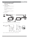
A termination resistor is typically NOT required when
a module is connected to the following controller
devices:
• Allegiant LTC 8500 Series main CPU bays
• Allegiant LTC 8600 Series main CPU bays
• Allegiant LTC 8800 Series main CPU bays
• LTC 8714 Series Allegiant Keyboard Expander
accessory units sold during or after 2002
If the supplied resistor is damaged or lost, any locally
obtained conventional 1/4 watt carbon resistor
between 120 ohm and 390 ohm should suffice.
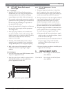
2. The POWER LED will light when AC power is
applied to the unit.
3. The DATA XTMR LED will flash as the external
data received by the unit is being optically
transmitted.
4. The DATA REC LED will flash as optical data is
being received by the unit.
IntuiKey Series
Keyboard
Keyboard
Data Cable
LTC 4671
RS485
DATA
REC
POWER
DATA
XTMR
- 4
- 3
-- Data - 2
+ Data - 1
AC
POWER
POWER
SUPPLY
AC
POWER
POWER
SUPPLY
LTC 8557
Junction Box
3
2
1
4
1
2
3
4
5
6
7
8
9
0
Sh
ot
Mo
n
Pro
d
Cl
r
BOSCH
ALLEGIANT Video System
CODE OUT
ALARM
STATUS
BATTERY LOW
POWER
Up to 4 km (2.5 mi) using
62.5/125 micron
Multimode Fiber Optic Cable
LTC 8557
Junction Box
3
2
1
4
To Allegiant Keyboard Port
Using Keyboard Data Cable
Typical Allegiant Main CPU Bay or Allegiant Keybord Port Expander
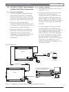
LTC 8557
Junction Box
3
2
1
4
Refer to Text
Regarding Supplied
120 Resistor
LTC 4771
RS485
TRANSCEIVER
XTMR
PWR
REC
BOSCH
1 2 3 4 5 6
POWER
IN from
RACK
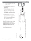
Side View
of Rear
Front
View
MONITOR
Separate Video
Transmission Link
1- Data "+"
2- Data "-"
LTC 4671/00
Rack-mount Model
(in LTC 4637 Card Cage)
POWER
- 2
+12VDC - 1
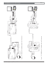
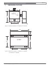
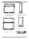
Figure 8 LTC 4671 Series Stand-alone Transceiver and LTC 4671 Rack-mount Transceiver
Typical Configuration: