


FMR-7036 | Fire Annunciator Keypad | 1.0 Notice
.
Bosch Security Systems, Inc. | 9/08 | F01U010584-01 3
1.0 Notice
These instructions cover the installation of the Bosch
Security Systems, Inc. FMR-7036 Fire Annunciator
Keypad in a fire system supervised by a Bosch FPD-
7024 Fire Alarm Control/Communicator.
Install, test and maintain the FMR-7036 according to
these instructions, NFPA 72, local codes, and the
authority having jurisdiction. Failure to follow these
instructions may result in failure of the device to
operate properly. Bosch Security Systems, Inc. is not
responsible for improperly installed, tested or
maintained devices.
NFPA 72 requires a complete system-wide
functional test be performed following any
modifications, repair, upgrades, or
adjustments made to the system’s
components, hardware, wiring,
programming, and software/firmware.
These instructions contain procedures to
follow in order to avoid personal injury and
damage to equipment.
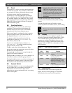
2.0 Device Description
The FMR-7036 is a four-wire LCD annunciator
keypad for the FPD-7024 Fire Alarm
Control/Communicator. It may be surface mounted
to a standard three-gang box or with the provided
mounting backplate.
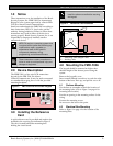
Figure 1: FMR-7036 Fire Annunciator Keypad
SILENCED TROUBLE
ALARM SUPERVISORY
LOCK
UNLOCK
FIRE SYSTEM ANNUNCIATOR
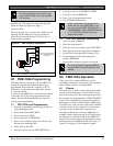
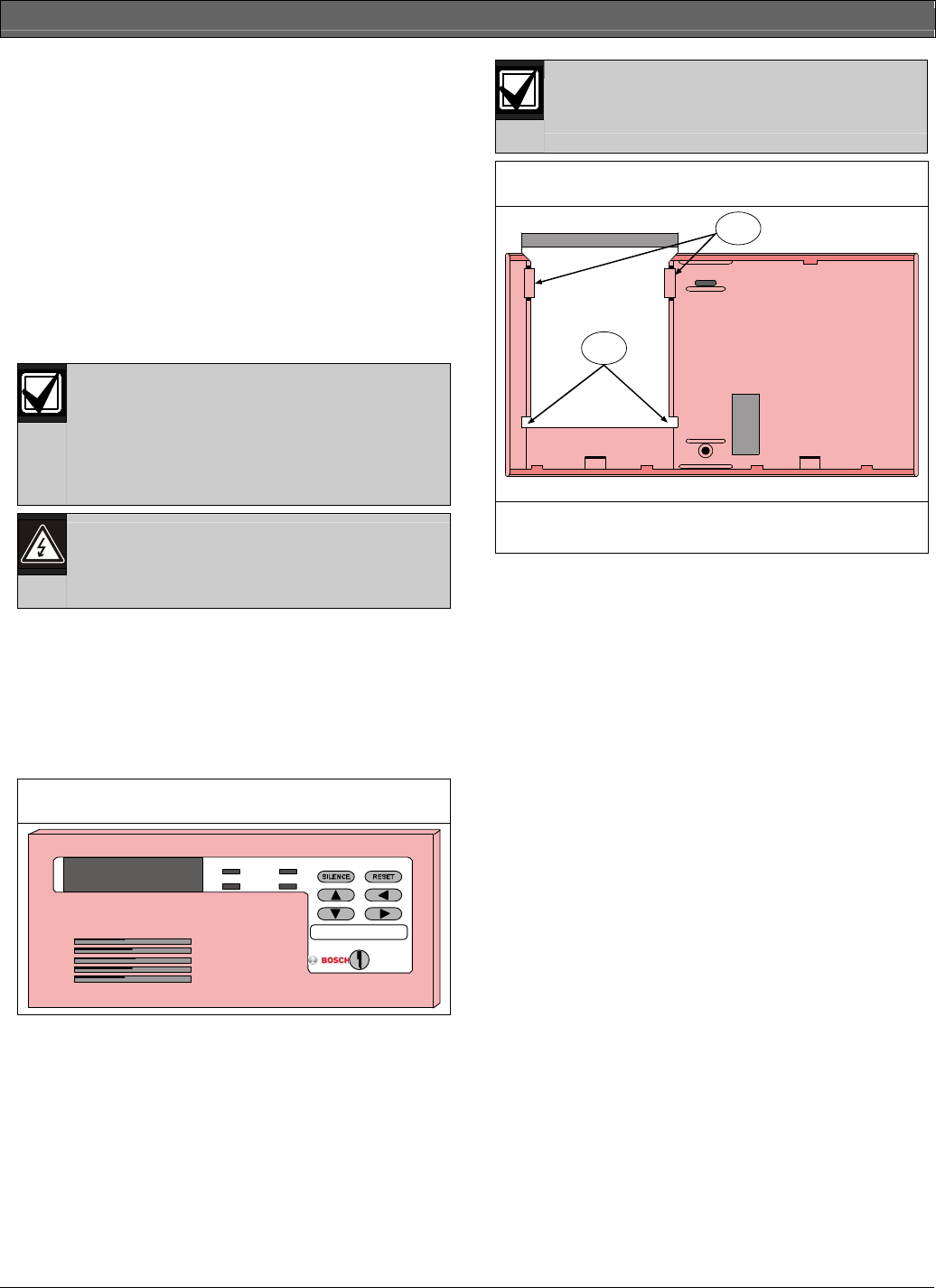
3.0 Installing the Reference
Card
A quick-reference card is provided and needs to be
installed in the receiving slot indicated in Figure 2.
The slot is located behind the mounting base
holding the circuit board.
Install the reference card before securing
the keypad.
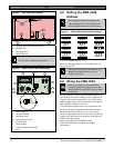
Figure 2: Reference Card Installation
FMR-7036 Reference Card
Slide reference guide between keypad holding tabs.
1
2
1 - Reference Card Stopper Tabs
2 - Holding Tabs
4.0 Mounting the FMR-7036
The keypad should be mounted no higher than
shoulder height of the shortest person using the
system.
Remove the keypad’s cover.
Insert a small flathead screwdriver in each slot at the
bottom of the base. Press up, and pull the cover off.
4.1 Surface Mounting
Use the base as a template to mark the location of
the mounting holes (refer to Figure 3 on page 4 for
mounting hole location).
Provide an opening in the mounting surface for the
wiring.
Pre-start the mounting screws.
Do not secure the base at this point.
4.2 Electrical Box Mounting
Refer to Figure 3 on page 4 for the location of the
mounting holes.