


Page 2 © 2011 Bosch Security Systems, Inc. DS794Z Installation Instructions
3.1 Bracket Mounting
NOTE: The use of the B334 Mounting Bracket (included) is strongly
recommended when installing this detector.
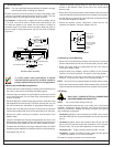
Because variations exist in the surfaces of most mounting walls, most
units are not mounted at perfect angles to the floor or walls. This may
cause the pattern to point away from the “ideal” direction.
For example: A shift of only 1 degree will cause a pattern shift of
1.7 ft. (0.52 m) at 100 ft. (30.5 m). Under worst case conditions, this
will cause the pattern to be aimed over the head of intruders at
maximum range, or into walls of narrow corridors. What may seem to
be poor range or catch performance, may be the result of improper
alignment.
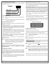
THREADED STUD
DS794Z BASE
B334 BODY
B334 COVER
NOTCH
WASHER EARS OUT
NOTCHED SIDE DOWN
CURVED WASHER
HEX NUT
Bracket to Base Assembly
Lock Washer
To insure proper catch performance, a bracket
mounted detector permits the flexibility needed to
properly adjust the direction of the coverage pattern.
If Mounting to the B334 Mounting Bracket:
• Remove the cover of the bracket by inserting a thin screwdriver into
the notch on the side of the bracket and twisting gently.
• Insert the alarm and power wiring through the center hole from the
rear of the B334 base. (Do not insert wiring if the bracket is to be
surface mounted).
• Mount the B334 to a standard single-gang switch or outlet box using
the supplied Bevel Head screws. (If surface mounting the unit, use
the wall screw/anchor assemblies or appropriate alternatives).
• Remove the circuit board from its base. Press the two circuit board
retainer tabs outward and lift the circuit board away from the base.
• Remove the sticker covering the entrance from the back of the
detector base.
• Insert the threaded stud through the appropriate stud hole in the
B334 bracket. Use the bottom hole for wall mounting or the front hole
for ceiling mounting. Make sure the hex head is seated in place.
• Complete the assembly by securing the detector base to the B334
bracket using the supplied curved washer and hex nut (see drawing).
• Hand tighten the hex nut.
• Thread the bracket wiring through the stud and along the wiring
channel in the detector’s base to the area of the circuit board’s
terminal strip.
• Return the circuit board to its base. Slide the back of the circuit board
under the tabs at the back of the base, then snap the front into place.
• Aim the detector in the desired general direction and tighten the hex
nut using the supplied hex wrench.
• Should the detector require realignment, loosen the hex nut,
reposition the detector, and then retighten the nut.
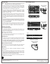
MOUNTING
HOLES (4)
WIRE ENTRANCE
STUD HOLE FOR
CEILING MOUNTED
BRACKET
STUD HOLE (HIDDEN)
FOR WALL MOUNTED
BRACKET
B334 Bracket
3.2 Surface or Corner Mounting
• Remove the circuit board from its base. Press the two circuit board
retainer tabs outward and lift the circuit board away from the base.
• Select and break away the appropriate thin-wall wire entrance
covering the detector base.
• Using the base as a template, mark the location of the mounting
holes on the mounting surface. Pre-start the mounting screws.
• Route the wiring to the rear of the base and through the wire
entrance. Firmly mount the base to the mounting surface.
NOTE: Be sure all wiring is unpowered (de-energized) before routing.
• Return the circuit board to its base. Slide the back of the circuit board
under the tabs at the back of the base, then snap the front into place.
4.0 Wiring
ONLY APPLY POWER AFTER ALL CONNECTIONS
HAVE BEEN MADE AND INSPECTED.
NOTE: Do not coil excess wiring inside unit.
Locate the two-piece terminal strip on the side of the circuit board
assembly. Remove the wiring connector from the terminal strip by
inserting a screwdriver between the wiring connector and terminal
strip, and gently prying apart.
• Terminals 1 (-) & 2 (+): Power limits are 6 to 15 VDC. Use no smaller
than #22 AWG (0.8 mm) wire pair between the unit and the power
source.
• Terminals 3, 4, & 5: Alarm relay contacts rated 125 mA, 28 VDC
maximum for DC resistive loads. Use terminals 4 & 5 for Normally
Closed circuits. Do not use with capacitive or inductive loads.
• Terminals 6 & 7: Tamper contacts rated at 28 VDC, 125 mA.
• Terminal 8: Trouble. Solid State Trouble output. Shorts to ground
(-) when the detector is in a Trouble condition.
Re-install the wiring connector to the terminal strip.