


DS794Z Installation Instructions © 2011 Bosch Security Systems, Inc. Page 3
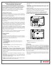
5.0 Configuration Switch Settings
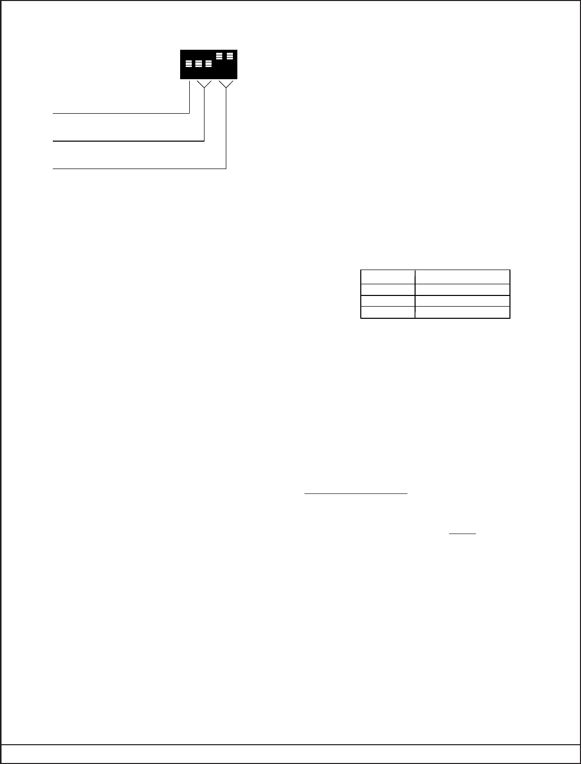
The DS794Z has several features that are controlled using the
configuration switches.
CONFIGURATION
SWITCHES
ON
OFF
1 ON
= LED ON
1 OFF
= LED OFF
2 ON
and 3 ON
= Standard Sensitivity
2 OFF and 3 ON
= Intermediate Sensitivity
2 ON and 3 OFF
= High Sensitivity
4 ON and 5 OFF
= 4 Day Motion Monitor
4 OFF and 5 ON
= 30 Day Motion Monitor
4 OFF and 5 OFF
= Motion Monitor Off
1 2 3 54
5.1 LED Operation (S1)
• ON: Allows the Alarm/Test LED to operate when activated by
motion.
• OFF: The LED will not operate on alarm activation, but will indicate
a supervision trouble condition.
5.2 Sensitivity Mode (S2 and S3)
Sensitivity modes depend on the type of coverage desired and the
installation environment.
• Standard Sensitivity: The recommended setting for the DS794Z
with the 80 ft. (24.4 m) Mirror installed. Tolerates environment
extremes on this setting. Not recommended for the 120 ft. (36.6 m)
and 200 ft. (61 m) coverages.
• Intermediate Sensitivity: The recommended setting for the 120 ft.
and 200 ft. (36.6 m and 61 m) coverages or for locations where an
intruder is expected to cover only a small portion of the protected
area. Tolerates normal environments on this setting.
• High Sensitivity: The setting for fast response to intruder signals.
For use in quiet environments where thermal and illumination
transients are not anticipated.
If both switches are in the Off position, the unit will default to the
Intermediate setting.
NOTE: Although the sensitivity modes provide different degrees of
tolerance to environmentally caused alarms, the installer
should assure peak background noise voltage readings do
not exceed ±0.15 VDC. (See Section 8.0 Final Tests).
5.3 Motion Monitor (S4 and S5)
Set switches S4 and S5 for the desired Motion Monitor time (see
Supervision Features). The detector is shipped with the Motion
Monitor feature Off.
6.0 Supervision Features
The DS794Z performs several supervision features that, combined
with the advanced motion detection capabilities of the detector,
provide an extremely high level of security. A supervision trouble
condition is indicated at the detector by the Alarm/Test LED (see the
Supervision Display Chart).
• The LED indicates the cause of the supervision trouble once per
second using coded pulses. The supervision trouble signal activates
the Trouble Output available on terminal 8.
The supervision features function as follows:
• PIR: The operation of the PIR is electronically checked approximately
every 12 hours. If the PIR fails, the Alarm/Test LED will flash 4 times
and the Trouble Output will activate.
• Motion Monitor Supervision: This feature verifies that the detector
has a clear view of the detection area. When selected using switches
S4 and S5, a supervision timer is activated. A trouble condition will
be indicated if the detector has not alarmed at least once during the
selected time period (this feature can be disabled by placing both
switches in the Off position). The time period selected should be
long enough to allow adequate time for holiday weekends.
Refer to Section 5.0 (Configuration Switch Settings) for proper
switch settings.
If the time period selected has elapsed from the last alarm, the LED
will flash 2 times and the Trouble Output will activate.
It is recommended that the 30 day timer be selected. This verifies
that the unit is operational and avoids nuisance trouble conditions
caused by holidays, vacations, etc.
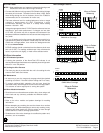
LED
ON
Flashing 2
Flashing 4
CAUSE
Unit Alarm
Motion Monitor Timeout
PIR Self-test Failure
Supervision Display Chart
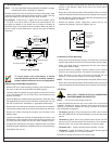
7.0 Setup and Walk Testing
If a different optical module is to be used:
• Slide the current module free from its housing. Install the new optical
module onto the housing. Make sure it snaps into place.
NOTE: Excessive handling of the front mirrored surfaces may lead
to performance degradation.
• Replace the front cover.
NOTE: All testing must be performed with the front cover in place.
• Apply power to the unit.
• Wait at least two minutes, after applying power, to start walk tests.
For best results, wait at least 1 minute between walk tests to allow
the processing to adjust to the background.
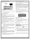
NOTE: Walk testing should be done across the coverage pattern as
shown.
• The edge of the coverage pattern is determined when the Alarm/Test
LED indicator (and optional Sonalert, if installed) first turns on.
NOTE: The use of a Sonalert type device (sounder) will provide an
audible tone during the time the unit is in alarm. Of the three
available connector pins, the center pin is positive (+) with
respect to either outside pin (outside pins are common (-)).
Walk test the unit from all directions to determine the boundaries.
• After completion of the walk tests, remove the Sonalert
(if installed).