


Page 2 © 2004 Bosch Security Systems DS422i/426i Installation Instructions
NOTE: Be sure all wiring is unpowered before routing.
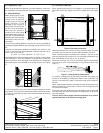
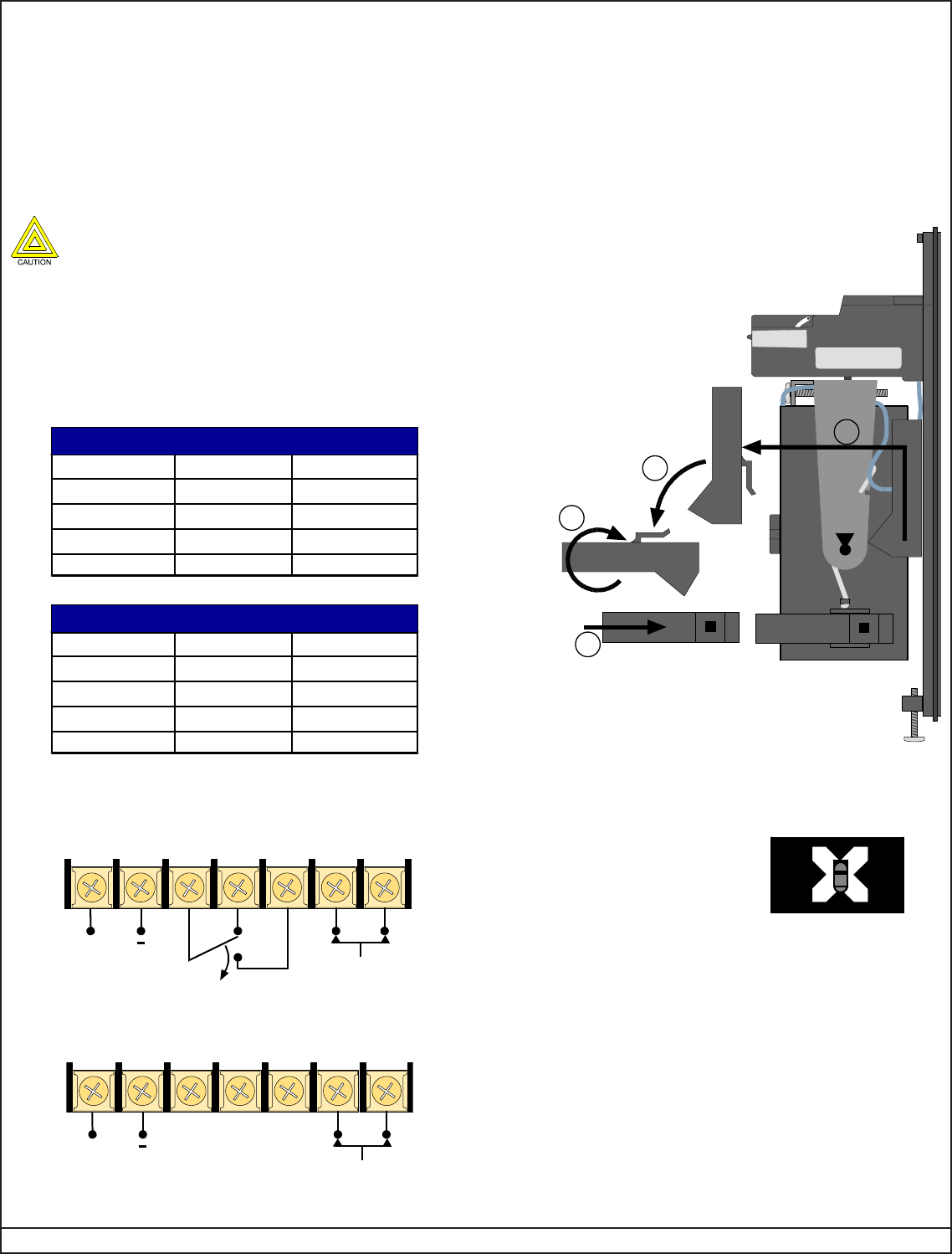
• Route wiring (for wire size see Section 4.0) through the mounting
plate wire entrance (see Figure B), leaving enough to properly wire
the transmitter.
• Route the wiring through the transmitter’s wire entrance.
• Slide the transmitter onto the mounting plate. Tighten with the
mounting plate-to-unit screws.
• Repeat this complete mounting procedure for the receiver. Be sure
to mount the receiver in direct-line-of sight with the transmitter.
4.0 Wiring
Only apply power after all connections have been made
and inspected.
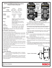
• Use the following chart (Figure C) to determine the minimum gauge
wire needed per length of wire run between the power source and
the last unit on the run. The chart is based on one system (one
transmitter and one receiver) connected to the same wire run from
the power source.
If more than one system is added to the run, the maximum length
per gauge decreases and is determined by dividing the length found
in the chart by the number of systems on the run.
Figure C - Wire chart
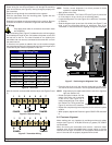
• Wire the receiver and transmitter terminal strips (see Figures D and
E).
12 5634 7
+
POWER ALARM TAMPER
Figure D - Receiver Wiring
Figure E - Transmitter Wiring
5.0 Setup and Alignment
NOTE: Precise, correct alignment is a critical process for these
systems to operate effectively.
• Apply power to the units.
• Check the transmitter. The Power LED (see Figure A) should be
on. If the lamp is not on, the unit is not receiving power.
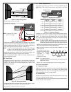
• Locate the Alignment Tool (see Figure A) on either the Transmitter
or Receiver.
• Slide the Alignment tool up and out of its holder (see Figure F) and
slide it onto the Alignment Mount on whichever side of the
Transmitter is most convenient for sighting through the viewfinder.
Figure F - Positioning the Alignment Tool
• From the side of the unit, look into the viewing port at the mirror.
The view in the mirror is what is in line-of-sight of the optical module.
NOTE: Alignment may be made easier with the use of an alignment
light (see Section 8.0).
• Rotate the optical module until the
image of the other unit is centered
in the mirror (see Figure G). If
initially aimed too high or low, adjust
the Vertical Fine Tuning screw (see
Figure A) until the unit is centered.
• Repeat this complete alignment sequence for the receiver’s optical
module.
• When properly aligned the Receiver’s green GOOD LED should be
lit.
6.0 Fine-tune Alignment
Meter readings are very important in providing maximum trip-safety
margins (see Figure H). A 20,000 Ohm/volt (or greater) DC VOM is
recommended.
When fine-tuning the transmitter and receiver, maximum meter
readings occur at the transmitted beam’s center, which is also the
receiver’s line-of-sight. A reduction in the system’s effectiveness will
occur if the units are not properly aligned and fine-tuned.
12 5634 7
+
POWER
TAMPER
SIZE
24 AWG(0.6mm)
22 AWG(0.8mm)
20 AWG(1.0mm)
18 AWG(1.2mm)
12 VDC
920 ft. (280m)
1,640 ft. (500m)
2,560 ft. (780m)
3,675 ft. (1120m)
24 VDC
790 ft. (240m)
1,440 ft. (440m)
2,300 ft. (700m)
3,280 ft. (1000m
)
DS422i Wiring Chart
SIZE
24 AWG(0.6mm)
22 AWG(0.8mm)
20 AWG(1.0mm)
18 AWG(1.2mm)
12 VDC
820 ft. (250m)
1,410 ft. (430m)
2,230 ft. (680m)
3,215 ft. (980m)
24 VDC
690 ft. (210m)
1,250 ft. (380m)
2,000 ft. (610m)
2,850 ft. (870m)
DS426i Wiring Chart
Figure G - Image in mirror
LOT.
OR
S
E
N
S
I
ER
TT
M
NS
AR
T
1
2
3
4