


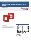

Functions
In the event of an alarm, the glass pane (2) is broken
first, then the pushbutton (3) is pressed hard. Thus
the switch triggers the alarm.
A locking mechanism holds the pressed manual call
point.
The pushbutton can be reset with the reset lever.
This does not reset the alarm on the fire panel.
Certifications and Approvals
Region Certification
Europe CE DM 1103
CE DKM2014
Germany VdS G 297060 DKM 2014/2-ex/-GLU
VdS G 295036 DM 1103 B-Ex
PTB 97 ATEX 3197 DKM 2014/2 / DKM
2014/2-GLU
Europe BASEE-
FA
Ex 98E2304 DM 1103 B-Ex
Installation/Configuration Notes
• Manual call points must be illuminated sufficiently
with daylight or another light source (including
emergency lighting, if present).
• An installation height of 1400 mm ±200 mm,
measured from the middle of the manual call point to
the floor, must be maintained.
• Manual call points must be installed along escape and
rescue routes (e.g. exits, passageways, stairwells).
• Further standards, guidelines and planning
recommendations regarding the installation location
etc., should also be taken into consideration (see Fire
Detection manual).
• Regulations of local fire departments must be
observed.
Installation/configuration notes in accordance with
VdS/VDE
• The distance between manual call points should not
exceed 100 m according to DIN 14675 or 80 m
according to VdS.
• In high risk areas, manual call points should be
installed at a distance of max. 40 m (VDE 0833 Part 2,
Point 7.2.6).
• According to VdS, up to 10 manual call points can be
connected to a primary line.
DKM 2014/2‑ex Manual Call Point Type K
• For connection to the LSN, an NBK 100 LSN Fire
Interface is required.
• Can be connected directly to the following
conventional control panels:
– BZ 1012
– BZ 1060
– UEZ 1000 GLT.
• With an NBK 100 LSN Fire Interface, can be
connected to the following control panels:
– BZ 500 LSN
– UEZ 1000 LSN
– UEZ 2000 LSN
– UGM 2020 LSN
DKM 2014/2‑ex‑UGM Manual Call Point Type K, for
Connection to UGM Conventional
• Can be connected directly to the UGM‑GLT Universal
Danger Detection System
DM 1103 B-Ex manual call point for ex area
• For connection to the LSN, an NBK 100 LSN interface
is required.
• For use in explosive areas of zones 1 and 2, a safety
barrier and an input/output module are required,
which must be mounted in front of the ex area.
• Cables can be inserted surface-mounted or flush-
mounted
Parts Included
Type Qt
y.
Components
DKM 2014/2‑ex 1 Manual Call Point Type K, for ex areas,
for surface mounting
DKM 2014/2‑ex‑UG
M
1 Manual Call Point Type K, for
Connection to UGM Conventional, for
ex areas, for surface mounting
DM 1103 B-Ex 1
1
2
DM 1103 B-Ex manual call point, color
red
Key for DM1103B-Ex manual call point
PG11 cable screws
Technical Specifications
DKM 2014/2‑ex Manual Call Point Type K
DKM 2014/2‑ex‑UGM Manual Call Point Type K, for
Connection to UGM Conventional
Operating voltage 24 V DC
Switch contact Type 366 (encapsulated), II 2 G
EEx d II C
Maximum contact load 5 A / 250 V AC
0,25 A / 250 V DC
Cable entry • 1x M16 x 1.5 tightening
diameter 4‑8 mm, EEx e II
• Blind plug: 1x M16 x1.5
EEx e II
Housing material Polyester, glass fiber reinforced
Colors Red, RAL 3001
Dimensions (W x H x D) 136 x 138 x 88 mm
Weight Approx. 1800 g
Protection class as per EN 60529 IP 66
Permissible operating
temperature
-25 °C to +40 °C
Ex classification Eex emd IIC T6
2 | Conventional Manual Call Points for Ex Areas