


D8229 | Installation Instructions | 4.0 System Startup
.
Bosch Security Systems, Inc. | 02/06 | 74-07324-000-D 3
When mounting the keypad outside, use a suitable
weatherproof back box.
3.2 Running the Cable
Install the D8229 up to 152 m (500 ft) from the
D9210B or 61 m (200 ft) from the D8210 using
0.6 mm (22 AWG) wire or up to 152 m (500 ft) from
the D8210 using 1.2 mm (18 AWG) wire. Run a six-
wire cable from the D8210 to the D8229 mounting
location. The D9201B can be installed 762 m
(2500 ft) using 0.6 mm (22 AWG) wire from the
control panel or 1524 m (5000 ft) using 1.2 mm (18
AWG) wire.
3.3 Splicing the Cable to the Wiring
Harness
Using solder or an equivalent means, splice the six-
wire harness, provided with the D8229, to the end of
the cable at the mounting location. Ensure each
spliced wire is properly covered with tape, or
insulation, so the conductors can not short to one
another, or to any grounded object.
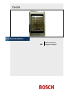
3.4 Plugging the Keypad into the
Cable Connector
The cable connector only plugs in one way. Plug the
cable connector assembly into the back of the
keypad before mounting the keypad.
3.5 Attaching the Keypad to the
Mounting Surface
Use the two #6 screws provided to attach the
keypad base to the back box. Tighten the mounting
screws.
Apply the Lexan labels.
4.0 System Startup
When programming the control panel is completed,
and all wiring is connected, power up the D8229.
Using the keypad, enter the four-digit PIN number
followed by the [#] key. If programming and wiring
are correct, access is granted.
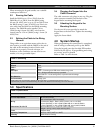
Refer to Table 1 to wire the unit.
Table 1: Unit Wiring
Input
Red
Ground
Black
Data 0
Green
Data 1
White
LED input
Brown – Controls green LED when switched to ground
Blue – Sink ground when any key is pressed
Case Gnd Tan – Local earth ground, to prevent static discharge
Site Selection
Yellow*
No Connections
Orange, pink
*If the yellow wire is connected to ground, the site code value = 1. If disconnected, the site code =0.
Bosch Security Systems recommends leaving the yellow wire disconnected and using a site code value of 0.
5.0 Specifications
Table 2: Specifications
Operating Voltage
5 VDC +/- 0.1 V 20 mA
Current Requirement
20 mA idle (nominal)
120 mA maximum (LED, illuminated)
Wiring
5 conductors (Data 1, Data 0, LED, Common, +5 or +12 VDC)
0.6 mm (22 AWG) = 152 m (500 ft) D9210B, 61 m (200 ft) D8210
1.2 mm (18 AWG) = 152 m (500 ft) D9210B, 152 m (500 ft) D8210
Dimensions (H x W x D)
13.0 cm x 8.6 cm x 1.1 cm (5.1 in. x 3.4 in. x 0.4 in.)
Weight = 0.7 kg (1.5 lb), ships at 0.9 kg (2 lb)
Finish
Stainless Steel
Operating Temperature
-40°C to +70°C (-40°F to +160°F)
Humidity
100% Relative Humidity