


24 VDC Applications
An auxiliary power supply is used in 24 VDC
applications. The auxiliary power supply provides
power for the module and all devices connected to the
two loops.
Notice
The power supply is not provided with the unit.
Any power supply installed must be UL listed for
use with Bosch fire products.
The D130 Relay Module is used for 24 VDC
applications. CMD 47 is used to reset 24 VDC smoke
detectors. Refer to the control panel's operation and
installation guide.
Unpowered initiating devices such as waterflow
switches, manual stations, and heat detectors are
installed without the D130 Relay Module.
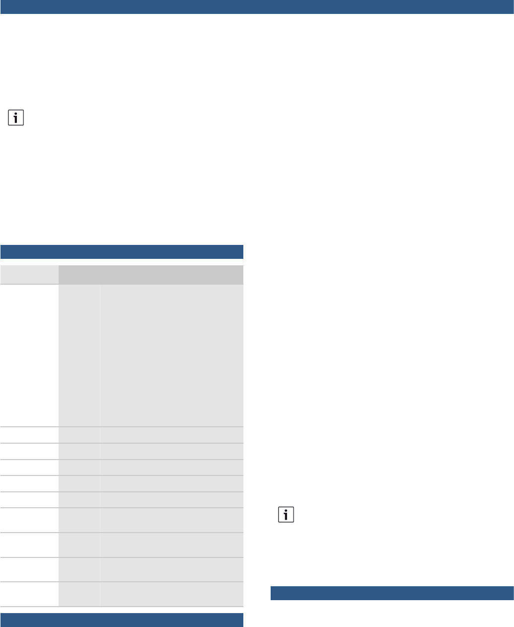
Certifications and approvals
Region Certification
USA UL AMCX: Central Station Alarm Units
(UL1610, UL1635), AMCX7: Central
Station Alarm Units Certified for Canada
(ANSI/UL 1635), AOTX: Local Alarm
Units (UL464, UL609), S525), APAW:
Police Station Alarm Units (UL365,
UL464), APAW7: Police-station-connec-
ted Alarm Units Certified for Canada
(CAN/ULC -S303, CAN/ULC-S304,
CAN/ULC-S525), APOU: Proprietary
Alarm Units (UL1076), NBSX: House-
hold Burglar Alarm System Units
(UL1023), UOJZ: Control Units, System
(UL864, 9th edition), UTOU: Control
Units and Accessories - Household Sys-
tem Type (UL985)
FM
CSFM 7165-1615:0238
CSFM 7165-1615:0242
CSFM 7167-1615:0239
CSFM 7167-1615-0243
FDNY-
CoA
6059
NYC-
MEA
12-92-E, Vol. IV 12-92-E, Vol. IV
NYC-
MEA
12-92-E, Vol. 12 12-92-E, Vol. 12
NYC-
MEA
12-92-E, Vol. 15 12-92-E, Vol. 15
Installation/configuration notes
Compatible Products
The following products are compatible with the D125B
Dual Class B Initiating Module:
Category Product ID Product Description
Control
Panels
G-series
1
Control panels
B-series
2
Control panels
D9412
3
,
D7412
3
,
D7212
3
Control panels
D9112B1
3
,
D7212B1
3
Control panels
D8112
3
Control panel
Detectors For a list of compatible two‑wire detectors, refer to the
D125B Installation Guide.
Enclosures D7103 Small enclosure (gray)
D8103 Universal enclosure (gray)
D8108A Attack-resistant enclosure (gray)
D8109 Fire enclosure (red)
Modules For a list of compatible modules, refer to the D125B
Installation Guide.
1
G-series = D9412GV4, D7412GV4, D7212GV4*, D9412GV3,
D7412GV3, D7212GV3*, D9412GV2, D7412GV2, D7212GV2*,
D9412G
3
, D7412G
3
, D7212G
3
*
2
B‑series = B5512 and B4512
3
These products are legacy products and have been investigated for
compatibility only to UL864 8
th
edition.
*
The D7212 models are not listed for commercial fire applications.
Mounting Considerations
The D125B module mounts in the Bosch control panel
enclosure using screws included with the unit. Use a
D137 Mounting Bracket to install additional modules
in the same enclosure, or when installing the D125B in
an approved adjacent enclosure. Separate enclosures
must be within 20 ft (6.1 m) of the control panel
enclosure and connected by conduit.
Wiring Considerations
Notice
When used in a fire system, NFPA 72 prohibits this
product from sharing a communications bus with
non-fire devices.
The D125B needs to be electrically connected to the
control panel's common terminal.
Parts included
Quant. Component
1 D125B module
2 1.8 kΩ EOL resistors (P/N: F01U009011)
1 Hardware pack
1 Literature pack
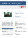
2 | D125B Dual Class B Initiating Module