


BISN0047.0 26/06/2007 Page 2
Installation
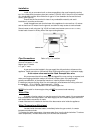
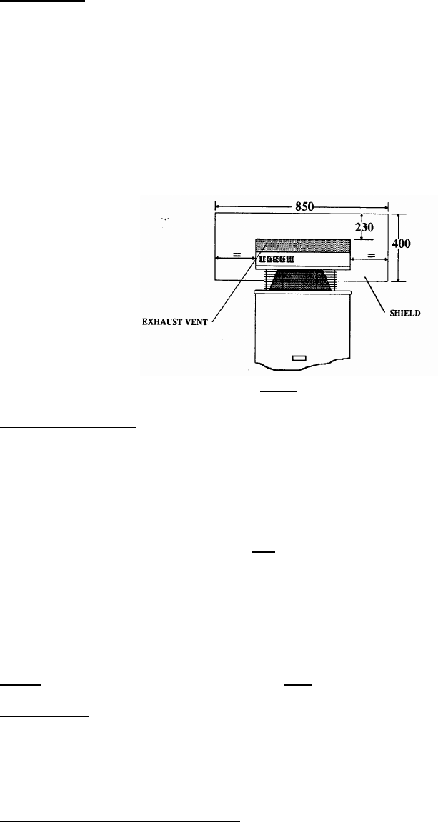
Install only on an external wall, as close as possible to the most frequently used hot
tap. Use a heat shield (accessory item part number 9 708 061 400) if the unit is to be installed
on a combustible surface. Allow minimum air gap of 10 mm between the flue and the heat
shield, (refer figure 2).
Ensure that the flue terminal is clear of any combustible material, and avoid
installation in a marine environment.
Install the appliance such that the base of the appliance is not more than 1.3 metres
and not less than 0.5 meters from the ground, and allow for easy access to service heater.
Secure heater to wall using two 10g X 5/16
hex head wood screws
(Ramset 610041 or similar)
.
Locate head of screw in the key hole of the top mounting bracket.
Fig. 2
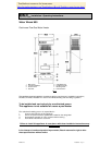
Pipe Connections
Refer to Fig. 1 for locations
Hot and Cold water ½" male
Natural gas ¾" female
L.P. gas ½" male
A gas cock must be installed in the gas supply line with provision to disconnect the
appliance. Install gate valve or full flow ball valve (fixed mechanism type) in cold water supply.
A non return valve must not be fitted. Example duo valve
We recommend that all hot water pipes be lagged if the runs are long or exposed, and
water-proof lagging should be used on all external hot water pipes. If the water supply
pressure exceeds 80% of the specified maximum, install a pressure limiting valve.
If installing a pressure limiting valve fit a cold expansion valve between the limiting valve and
the appliance. PLV = 500kPa Cold expansion = 700kPa
Refer to AG 601 and AS3500.1 for the relevant pipe size.
NOTE:Service calls for incorrect pipe sizing will NOT be covered under warranty.
Water Filter
If sludge or foreign matter is or may be present in the water supply, it is recommended
that a suitable filter be incorporated in the water supply line to the heater. All pipes should be
well flushed before connection is made.
A water filter/strainer is installed in the inlet of the brass water valve inside the appliance.
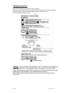
Water Temperature Adjustment
Located inside the water heater, immediately below the gas controls, is a water
temperature selector knob.
To increase the water temperature ( decrease water flow ) turn the knob clockwise. To reduce
water temperature ( increase water flow ) turn the knob anti clockwise.