


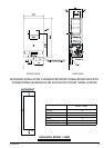
116 720 606 518
The water heater must be isolated from the gas supply piping
system by closing the manual shutoff valve during any
pressure testing of the gas supply piping system at test
pressures equal to or more than 0.5 psig.
The water heater, including the pressure regulator provided
with it, must not be operated at gas supply pressures in
excess of 0.5 psig. If overpressure has occurred, such as
through improper testing of the gas lines or malfunction of
the supply system, the gas valve and regulator must be
checked for safe operation. Make sure that the regulator
vent is protected against blockage.
When your connections are made, check for gas leaks at
all joints (not just the ones you made). Apply some soapy
water to all gas fittings and gas valve. Soap bubbles are a
sign of a leak.
NOTE: Do not apply soap solution to pilot filter screen or
pilot orifice area. If you have a leak, shut off the gas. After
verifying that required gaskets are in place, tighten
appropriate fittings to stop leak. Turn the gas on and check
again with a soapy solution. Never test for gas leaks using
a match or flame.
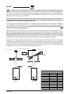
WATER CONNECTIONS
Install the heater centrally in the building if possible and
make hot water piping runs as short as possible When facing
the heater, the cold water inlet will be on the right and the
hot water outlet on the left..
Although water piping throughout the building may be other
than copper, copper or galvanized piping should be used
when connecting to the heaters ½” male NPT flex connectors
(follow local codes if more stringent). Plastics or other PEX
type plumbing line materials are not suitable for connecting
directly to the water heater. Keep water inlet pipe to no less
than ½” (19.05mm) diameter to allow the full flow capacity.
If the cold and hot connections to the heater are reversed,
the heater will not function.
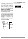
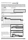
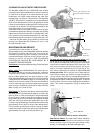
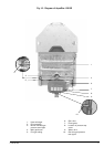
The Aquastar 125BS is provided with two flexible type
connectors that must be connected to the fittings of the
water valve as shown in Fig. 6. The union end of the flexible
connectors should be attached to the rear inlet ports of the
water valve with the supplied washer gaskets. No pipe dope
or thread tape is to be used at these joints.
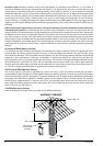
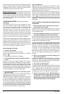
Be certain there are no loose particles or dirt in the piping.
Blow out or flush the lines before connecting to the water
heater. Full port valves should be installed on both the cold
water supply and hot water outlet lines to facilitate servicing
the heater (see Fig. 7). For installation on a private well
system with the use of a pressure tank, the lowest pressure
range setting recommended is 30-50 psi (2.07-3.45 bar).
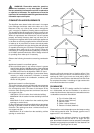
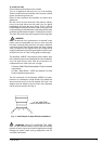
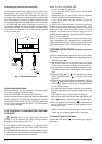
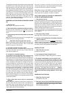
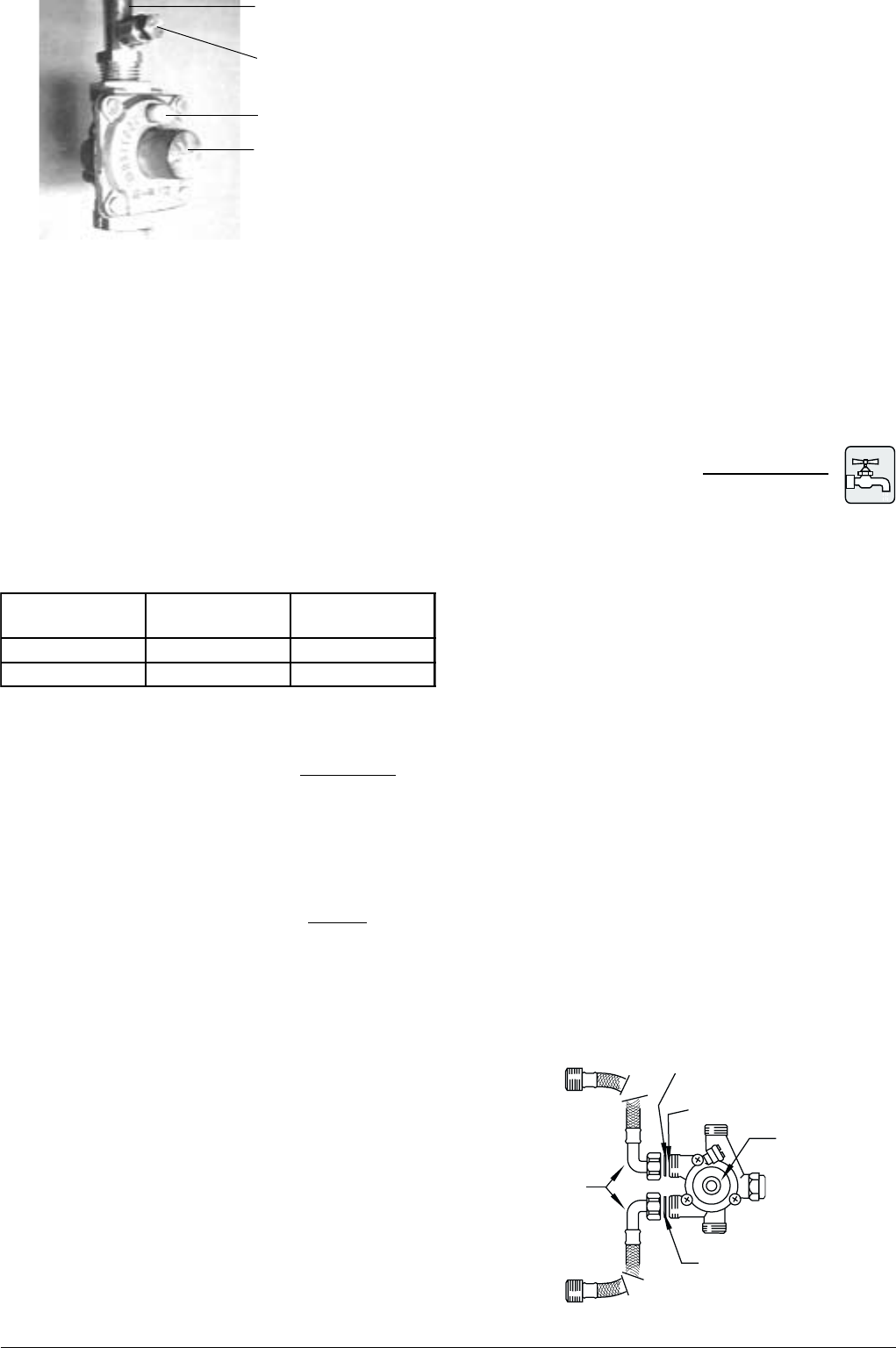
Fig. 5 - Installation of Gas Pressure Regulator
The pressure regulator provided with the heater is adjusted
to deliver the proper gas pressure (as indicated on the rating
plate and in the manual for altitude up to 2000 feet (660
meters) above sea level. On appliances being installed above
2000 ft (660 meters) elevation, the inlet gas pressure should
be set at installation to the value shown below.
NOTE: The gas pressures specified below refer to
pressures taken at the test pressure tap on the gas inlet
pipe just above the regulator (See Fig 5). These readings
should be taken while the heater is operating at full input
— i.e. maximum water flow with the temperature dial
selector turned all the way clockwise.
MAXIMUM INLET GAS FLOW PRESSURE SETTING
Altitude Natural Gas Liquid Propane
inches W.C: inches W.C:
0' - 2.000 ft 5.7" 10.5"
2.000 ft - 4.500 ft 4.6" 8.4"
Above 4.500 ft consult your local gas supplier.
GAS INLET PIPE
PRESSURE TAP
PRESSURE REGULA-
TOR
(with directional arrow on
reverse side pointing
upward)
PLASTIC VENT CAP
GAS LINE SIZING
-It is strongly recommended that the Natural Gas pipe
be Black Iron pipe the entire distance from the outside
meter to the inlet of the Aquastar regulator. 1/2” Black
Iron pipe up to 10 feet, 3/4” Black Iron pipe up to 40 feet
and 1” Black Iron pipe up to 150 feet distances. Flex line
tubing is NOT recommended, but if used then oversize
it.
-It is strongly recommended that the LP Gas pipe be
semi-rigid copper or Black Iron pipe from the outside
regulator to the inlet of the Aquastar regulator. For semi-
rigid copper piping: 5/8” up to 20 feet and 3/4” up to 60
feet distances. For Black Iron piping: 1/2” up to 45 feet
and 3/4” up to 160 feet distances. Flex line tubing is NOT
recommended, but if used then oversize it.
THESE FIGURES ARE FOR AQUASTAR SUPPLY ONLY, ALL
OTHER APPLIANCES IN THE BUILDING WILL NEED TO
BE INCLUDED IN THE PIPE SIZING.
National Fuel Gas Code requires that a sediment trap (drip
leg) be installed on gas appliances not so equipped. The
drip leg must be accessible and not subject to freezing
conditions. Install in accordance with the recommendations
of the serving gas supplier.
WARNING: The heater must be disconnected from the gas
supply piping system during any pressure testing of that
system at test pressures in excess of 0.5 psig.
Fig. 6 - Water valve and water connectors, top view
WASHER
WATER FILTER
WATER VALVE
WASHER
INLET
OUTLET
FLEX
CONNEC-
TORS