


14
WARNING: Do not at any time make any
adjustment to the unit without first
stopping engine and disconnecting
spark plug wire.
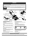
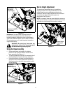
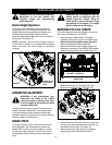
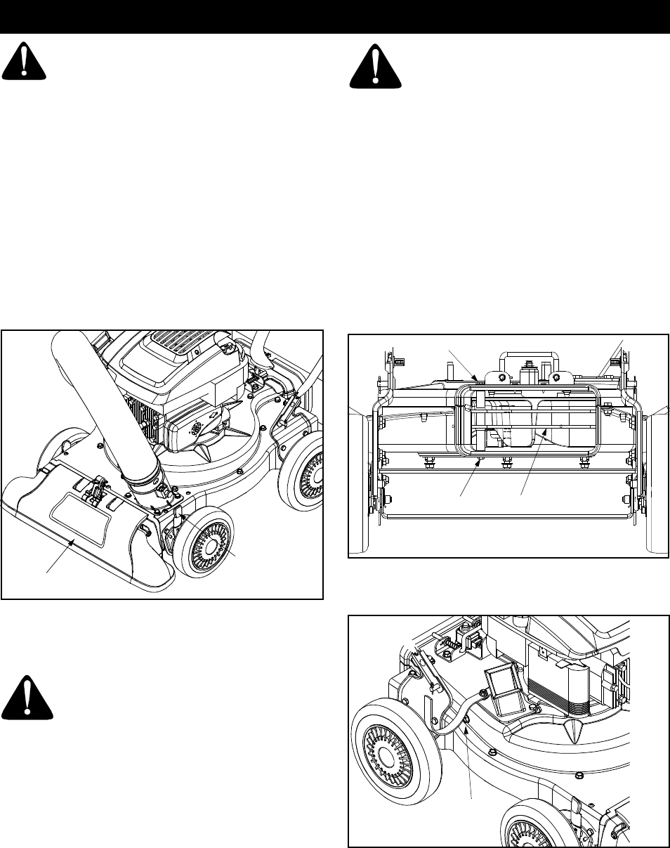
Nozzle Height Adjustment
The nozzle can be adjusted to any six positions,
ranging from 5/8” to 4 1/8” ground clearance. The
nozzle height has to be adjusted according to the
conditions. Move the height adjustment levers
forward or backward to adjust the nozzle upwards or
downwards. See Figure 14.
NOTE: In general, raise the nozzle height to vacuum
a thick layer of leaves or to operate with the blower
chute and lower the nozzle height for smoother
surfaces.
Figure 14
CARBURETOR ADJUSTMENT
WARNING: If any adjustments (e.g.
carburetor) are made to the engine
while the engine is running, keep clear
of all moving parts. Be careful of heated
surfaces and muffler.
The carburetor has been pre-set at the factory and
should not require adjustment. If your engine does
not operate properly due to suspected carburetor
problems, take your Yard Vacuum to a Sears Service
Center for repair and adjustment.
ENGINE SPEED
The engine speed on your Yard Vacuum has been
set at the factory. Do not attempt to increase the
engine RPM. If you think that the engine is running
too fast or too slow, take your Yard Vacuum to the
nearest Sears Service Center for repair and adjust-
ment.
WARNING: Do not attempt to alter the
engine speed by tampering with the
engine’s governor linkage. Doing so
could result in serious personal injury
and damage to the engine. The engine
RPM has been set at the factory.
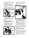
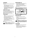
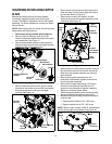
REMOVING THE FLAIL SCREEN
If the discharge area becomes clogged, remove the
flail screen and clean area as follows.
• Stop the engine. Make certain the chipper
shredder vacuum has come to a complete stop.
• Disconnect and ground the spark plug wire
before unclogging the discharge chute.
• Remove the vacuum bag or blower chute from
the unit as instructed in the OPERATION section
to obtain access to flail screen. See Figure 15.
Figure 15
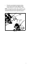
• Remove hex screw on right side of unit that
attaches to the flail screen. See Figure 16.
Figure 16
• Remove hex screw and flat washer on top of rear
housing near mounting bracket and the lock nut
that secures flail screen. See Figure 15.
• Remove and clean the screen by scraping or
washing with water. Reinstall the screen.
Nozzle
Nozzle Height
Adjustment
Lever
Flail Screen
Lock Nut
Hex Screw & Flat Washer
REAR VIEW
Remove
Hex Screw
SERVICE AND ADJUSTMENTS