


www.bockwaterheaters.com
110 South Dickinson Street , Madison, Wisconsin 53703
Toll Free 800.794.2491
•
Phone 608.257.2225
●
Fax 608.257.5304
80031 Rev 3/08
Dielectric Fittings: Factory Installed
T&P Valve: Factory Installed
Brass Drain Valve: Factory Installed
Relief Valve Opening: 3/4”
Hand-hole Cleanout Opening: Standard
Pressures (all): Working Pressure, 150 psi;
Testing Pressure, 300 psi
Warning: Do not install on combustible ooring.
Installation should be in accordance with all
national and/or local codes. In the absence of
local codes, refer to NFPA 31, NFPA 54 or ANSI
Z.21.10.1.
Caution: The recommended maximum hot water
termperature setting for normal residential use is
120°F. Bock recommends a tempering valve or
anti-scald valve be installed and used according to
the manufacturer’s directions to prevent scalding.
Energy Saver
120
80
50
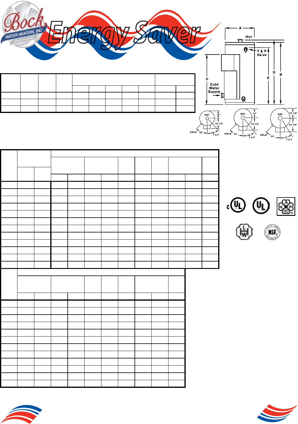
Dimensions and Capacities
Model
Storage
(gal)
kW
Input
Inlet
Pipe
Dia.
Dimensions
Shipping Weight
(lbs)
A B C D E Standard ASME
50F-* 50 ** 1-1/2 24 47-3/4 46-1/2 49-1/4 41 270 302
80F-* 80 ** 1-1/2 26 60-1/4 46-1/2 61-3/4 52-1/2 335 378
120F-* 119 ** 1-1/2 30-1/4 64-1/2 50-1/4 66 55 430 485
*When order surface mounted thermostat, add the letter “S” before the “F”. Example 50SF
*When ordering the Immersion thermostat add the letter “C” before the “F”. Exampe 50CF
*For ASME construction add an “A” to the model number. Example 50CF-A
**Add a “6”, “9”, “12”, “13.5”, “15”, “18”, “24”, “27”, “30”, “36”, “45”, or “54” to the model number to indicate kW
input desired. Example 50S(C)F-6
Where Applicable
Operating Characteristics
Recovery
@
Full Load Current Amperes (Fused Models)***
kW
Input
208 Volts
Phase
240 Volts
Phase
277
Volts
Phase
380
Volts
Phase
415
Volts
Phase
480 Volts
Phase
600
Volts
Phase
90°F
Rise
100°F
Rise
1 3 1 3 1 3 3 1 3 3
6 28 25 28.8 16.6 25 14.4 21.6 10 9 12.5 7.2 5.8
9 42 37 43.2 25 37.2 21.6 32.4 14 13 18.7 10.8 8.7
12 55 50 57.6 33.3 50 28.9 43.3 19 17 25 14.4 11.5
13.5 62 56 64.9 37.5 56.2 32.5 48.7 21 19 28.1 16.2 13
15 69 62 72.1 41.6 62.5 36.1 54.1 23 21 31.2 18 14.4
18 83 74 86.5 50 75 43.4 64 28 25 37.5 21.6 17.3
24 110 99 115.4 66.7 100 57.8 86.6 37 34 50 28.9 23.1
27 124 112 129.8 75 112.5 65 97.4 41 38 56.2 32.5 26
30 138 124 144.2 83.3 125 72.2 108.3 46 42 62.5 36.1 28.9
36 165 149 173 100 150 86.7 129.9 55 50 75 43.3 34.6
45 207 186 216.3 125 187.5 108.3 162.4 69 63 93.7 54.1 43.3
54 248 223 259.6 150 225 130 194.9 83 75 112.5 65 52
Number of Elements (Fused Models)***
kW
Input
208 Volts
Phase
240 Volts
Phase
277
Volts
Phase
380
Volts
Phase
415
Volts
Phase
480 Volts
Phase
600
Volts
Phase
1 3 1 3 1 3 3 1 3 3
6 3(2) 3 3(2) 3 3 3 3 3(2) 3 3
9 3 3 3 3 3 3 3 3 3 3
12 3 3 3(2) 3 3 3 3 3(2) 3 3
13.5 3 3 3 3 3 3 3 3 3 3
15 3 3 3 3 3 3 3 3 3 3
18 3 3 3 3 3 3 3 3 3 3
24 4 6 4 6 4 6 6 4 6 6
27 6 6 6 6 6 6 6 6 6 6
30 6 6 6 6 6 6 6 6 6 6
36 6 6 6 6 6 6 6 6 6 6
45 9 9 9 9 9 9 9 9 9 9
54 9 9 9 9 9 9 9 9 9 9
Units with amperage draw of 48 amps or more require factory installed internal fusing.
***If the number of elements on non-fused models is different, it is indicated in parentheses (), following the AMP draw.