


3. Installation of Voltmeter Wires: Wire the meter as shown below, making certain to attach
the hot lead to the terminal on the meter marked “+” and the neutral lead to the terminal marked
“-”. Use a minimum 16 AWG wire, black for hot and white for neutral. Verify that the circuit
protection device (circuit breaker or fuse) protecting the circuit to be monitored will also protect
the 16 AWG meter sensing wires. If it is oversized, install a 1 ampere fuse in the hot lead near
the source. Do not connect the voltmeter in a serial (in-line) confi guration.
Wiring Diagram
for AC Voltmeters
(
Installation (continued)
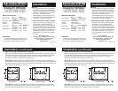
4. Calibration
The voltmeter is calibrated at the factory and recalibration should never be necessary. However,
if adjustment does become necessary the needle may be reset to the zero mark.
In the center of the black area on the meter front is an adjustment screw. This screw activates a
small cam that defl ects the meter needle slightly to adjust the needle position.
Using a small screw driver, turn the screw no more than 90 degrees right or left, as necessary.
DO NOT ROTATE THE ADJUSTMENT SCREW THROUGH 360 DEGREES.
PN 8244 / PN 8245 PN 9353 / PN 9354 Surface Mount Panel Mount
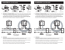
3. Installation of Voltmeter Wires: Wire the meter as shown below, making certain to attach
the hot lead to the terminal on the meter marked “+” and the neutral lead to the terminal marked
“-”. Use a minimum 16 AWG wire, black for hot and white for neutral. Verify that the circuit
protection device (circuit breaker or fuse) protecting the circuit to be monitored will also protect
the 16 AWG meter sensing wires. If it is oversized, install a 1 ampere fuse in the hot lead near
the source. Do not connect the voltmeter in a serial (in-line) confi guration.
Wiring Diagram
for AC Voltmeters
(
Installation (continued)
4. Calibration
The voltmeter is calibrated at the factory and recalibration should never be necessary. However,
if adjustment does become necessary the needle may be reset to the zero mark.
In the center of the black area on the meter front is an adjustment screw. This screw activates a
small cam that defl ects the meter needle slightly to adjust the needle position.
Using a small screw driver, turn the screw no more than 90 degrees right or left, as necessary.
DO NOT ROTATE THE ADJUSTMENT SCREW THROUGH 360 DEGREES.
PN 8244 / PN 8245 PN 9353 / PN 9354 Surface Mount Panel Mount