


31
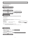
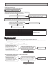
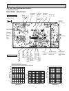
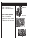
10-6. TEST POINT DIAGRAM AND VOLTAGE
-4 14 32 50 68 86 104
0
10
20
30
40
50
60
70
80
90
100
Temperature(°F)
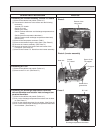
Defrost thermistor(RT61)
Ambient temperature thermistor(RT65)
Outdoor heat exchanger temperature thermistor(RT68)
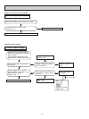
Temperature(°F)
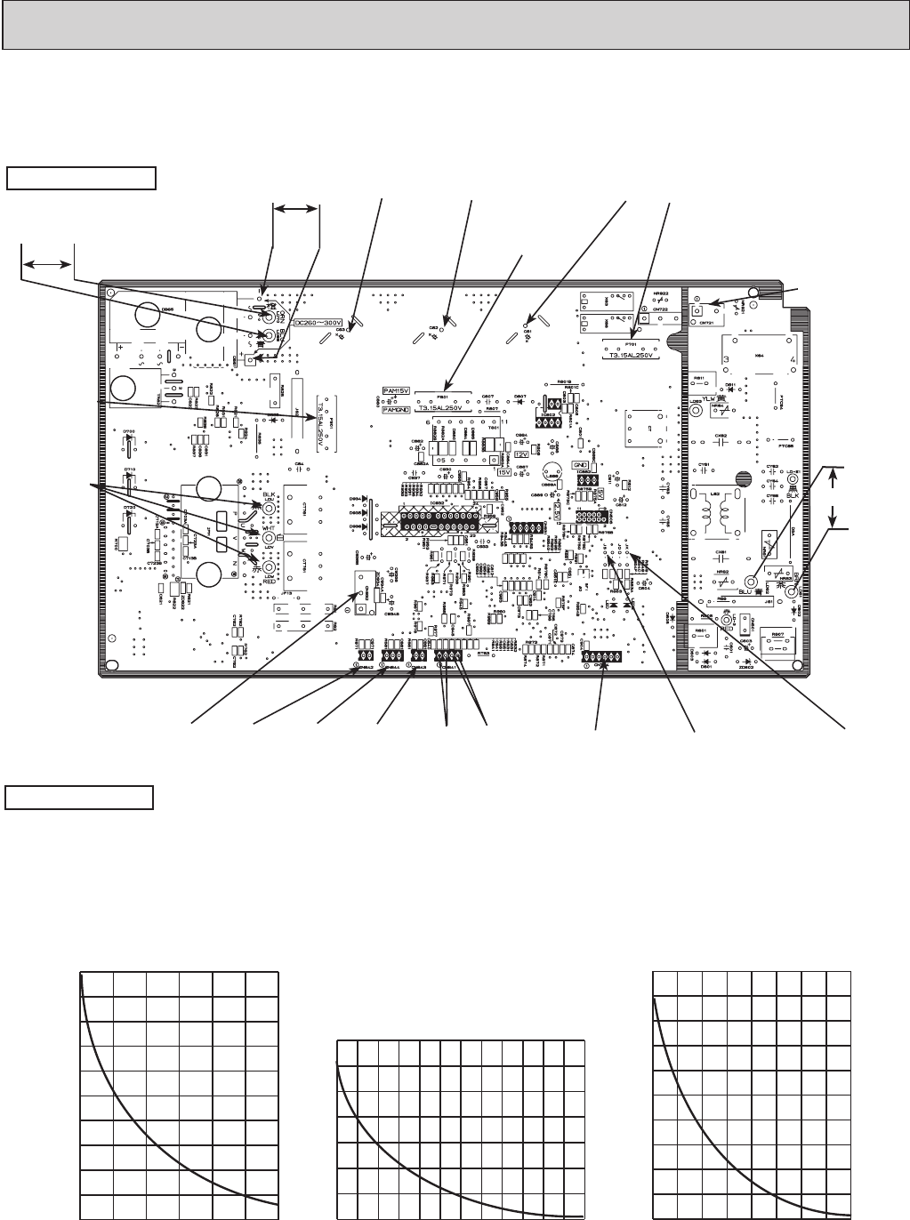
Discharge temperature thermistor(RT62)
32 50 68 86 104 122 140 158 176 194 212 230 248
0
100
200
300
400
500
600
700
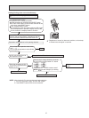
32 50 68 86 104 122 140 158 176
0
20
40
60
80
100
120
140
160
180
200
Temperature(°F)
Fin temperature thermistor(RT64)
Resistance(kΩ)
Resistance(kΩ)
Resistance(kΩ)
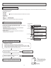
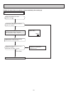
1. Inverter P.C. board
MUZ-FD09NA MUZ-FD12NA
Back side of unit
Fin temperature
thermistor /RT64
(CN642)
Ambient temperature
thermistor /RT65
(CN643)
Discharge temperature
thermistor /RT62
(CN641)
Defrost thermistor
/RT61(CN641)
LEV
connector
(CN724)
DB61
DC260 ~300 V
Front side of unit
AC 208 / 230 V
Smoothing
capacitor
(C62)
Output to
drive com-
pressor
(LDU,
LDV,
LDW)
(+)
(-)
Fuse(F701)
250 V 3.15 A
Smoothing
capacitor
(C61)
Smoothing
capacitor
(C63)
Fuse(F801)
250 V 3.15 A
R.V.coil
(CN721)
208 / 230 VAC
Jumper wire for
changing defrost
setting (JS)
Output to drive outdoor
fan motor (CN932)
AC208/230 V
Outdoor heat exchanger
temperature thermistor
/RT68(CN644)
Jumper wire
for pre-heat
control setting
(JK)
Fuse(F901)
250 V 3.15 A