


724-746-5500 | blackbox.com
Page 10
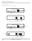
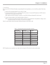
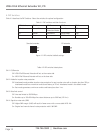
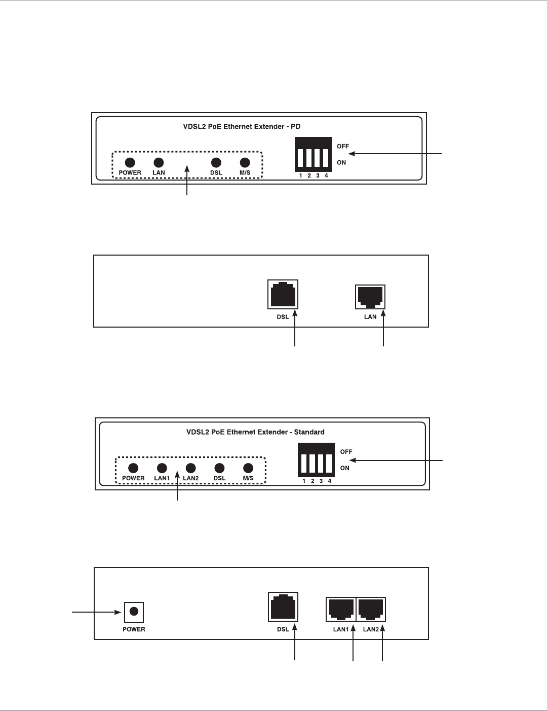
2.6 Front and Back Panels
Figures 2-2 through 2-5 show the extenders’ front and rear panels.
Figure 2-2. Front panel, VDSL2 PoE Ethernet Extender (PD), PD unit.
Figure 2-4. Front panel, VDSL2 PoE Ethernet Extender (PD), Standard unit.
Figure 2-3. Rear panel, VDSL2 PoE Ethernet Extender (PD), PD unit.
Figure 2-5. Rear panel, VDSL2 PoE Ethernet Extender (PD), Standard unit.
RJ-11 Connector
RJ-45 Connector
LED Indicators
DIP Switches
LED Indicators
DIP Switches
RJ-11 Connector
Power Input
RJ-45 Connectors
VDSL2 PoE Ethernet Extender Kit, PD