


724-746-5500 | blackbox.com724-746-5500 | blackbox.com 724-746-5500 | blackbox.com
Industrial Grade 4-Port USB Hub Industrial Grade 4-Port USB HubIndustrial Grade 4-Port USB Hub
Page 3Page 2 Page 4
What’s Included
Your package should include the following items. If
anything is missing or damaged, contact Black Box
Technical Support at 724-746-5500 or
info@blackbox.com.
• (1) Industrial Grade 4-Port USB Hub
• (1) USB cable
• (2) panel-mount adapters and (4) mounting screws
• (1) DIN rail adapter and (3) mounting screws
• This quick start guide
NOTE: A power supply is not included.
Overview
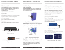
Figure 1 shows the front view of the hub. Figure 2
shows the side view.
To USB host
LED
indicators
Downstream
ports
Figure 1. Front view.
Detachable
terminal block
Power plug
Figure 2. Side view
Installation Steps
Step 1: Mounting
DIN rail mounting: Attach the DIN rail bracket with
the flat surface of the bracket facing the back of the
hub, as shown in Figure 3.
DIN rail
bracket
Figure 3. DIN rail bracket attached to hub.
Panel mounting: Attach the panel-mount brackets to
either side of the hub. They can be attached in (4)
positions: up, down, forward, and back.
Panel-mount
brackets
Figure 4. Panel-mount bracket positions.
Step 2: Connect the Power Supply
ICI200A: The non-isolated Industrial Grade 4-Port USB
Hub (ICI200A) can operate without an external power
supply. When the hub is running on USB power,
it provides a maximum of 100 mA to each of the
downstream ports.
ICI202A: Unike the non-isolated hub, the isolated
Industrial Grade 4-Port USB Hub (ICI202A) will not
operate without an external power supply. You can
use the detachable terminal block input or the locking
barrel jack. The terminal block is polarity protected.
When powered, the ICI200A and ICI202A will provide
500 mA to each downstream port. They require 10
to 30 VDC of external power and will consume a
maximum of 16 W.
NOTE: The ICI202A adds 4-kV isolation.
Step 3: Grounding
We recommend that you ground the chassis. Connect
a grounding wire from the green ground lug to a
good source of earth ground.
Figure 5. Grounding the chassis.
Step 4: LED Status
Figure 6 shows the LEDs on the ICI200A and ICI202A.
Table 1 describes their functions.
Figure 6. Left: ICI200A; right: ICI202A.