


grill ring snap into position, holding the grill
together. The grill ring must fit evenly
around the front and rear grills. If it does
not, remove the front grill and check the
alignment of the ring on the front grill.
11. Secure the guard using the screw (Q),
washer (R) and clip (S) by inserting the
screw, from the front, through the hole in the
bottom of the guard ring. From the back, put
the washer and clip, which has a threaded
hole, onto the screw, ensuring the clip is the
correct way to fit into the recess on the fan
ring. Tighten the screw fully but do not
overtighten.
OPERATING INSTRUCTIONS
1. Set fan on a dry, level surface.
2. Plug cord into any standard 220-240 volt
outlet. Please make sure the speed control
is in the off position.
For BASF17V only
1. The SPEED is adjusted by pressing the
Control Pad button (W) to the desired
setting:
Off (O) - High (III) - Med (II) - Low (I)
2. The OSCILLATION control (T) is located on
the top of the fan motor housing. To start
oscillation, push the control know down. To
stop oscillation, pull the control knob up.
For BASF17VRC only
REMOTE CONTROL
The Remote Control requires 2 AAA batteries for
operation.To install the batteries (not included),
simply depress the back of the remote, with
your thumb in the indentations, and remove the
cover. Insert the batteries according to the
diagram shown inside. Replace the cover.
All function keys are enabled after pressing the
On/Speed key, using the Remote Control unit
(V) or the Control Pad (W).
On/Speed ( )
1. To turn the fan On press the On/Speed
button. The fan will start to operate at the
low speed. You may now choose alternative
settings.
2. The fan will be turned Off when you press
the Off ( ).
3 By pressing the On/Speed button, you can
choose 3 different speeds; successive
presses of the On/Speed button cycles the
fan through the 3 speeds available.
4 The LED lamp on the Control Pad indicates
the selected speed stage (III-II-I).
Timer ( )
1 You can choose different timer stages by
pushing the Timer button.
2 The LED lamp on the Control Pad indicated
the selected time in hours. After the selected
time the fan will stop automatically.
3 If no timer LED lamps are lit, the fan will run
constantly.
4 The memorized time displayed on the
keypad is cumulative, i.e. if the 1 hour and
0.5 hour LEDs are lit the fan will switch off
after 1.5 hours. The maximum memorized
time is 7.5h, each press of the Timer button
adds 0.5 of an hour.
Oscillation ( )
By pressing the Oscillation button, the fan
begins to oscillate. Re-press the button to stop.
Breeze Mode ( )
By pressing the Breeze Mode key, different
functions can be chosen.
1. Natural Breeze Mode ( )
(press Breeze Mode button once).
The Mode LED flashes and the fan operates
at different speed stages alternately, to imitate
a natural breeze. To de-activate the Natural
breeze mode function switch the fan off.
2. Sleeping Breeze Mode ( )
(press Breeze Mode button twice)
Sleeping breeze mode can be used in
association with the Timer (see above Timer
section for details). By setting different timer
durations at Sleeping breeze mode, the fan
operates at decreasing speed stages until
the memorized timer duration is reached. The
LED lamp is continuously on. To de-activate
the Sleeping breeze mode function switch
the fan off.
ADJUSTMENT INSTRUCTIONS
Fan Head Tilt-Adjustment
1. To change the tilting angle of the fan head,
simply loosen the tilt-adjustment knob (U).
2. Move the fan head to the desired angle and
firmly tighten the tilt-adjustment knob (U) to
lock into place.
Height adjustment
Follow these instructions to adjust the height of
the fan.
1. Turn the pole locking knob (E) anticlockwise
to loosen the pole.
2. Adjust the pole to the desired height and
firmly tighten the locking knob in a clockwise
direction.
CLEANING AND MAINTENANCE
• Always unplug the fan before cleaning or
disassembly.
• Do not allow water to drip on or into the fan
motor housing.
PLEASE READ AND SAVE THESE
IMPORTANT INSTRUCTIONS
When using electrical appliances, basic safety
precautions should always be taken including
the following:
• Use the fan only for purposes described in
the instruction manual.
•To protect against electrical shock, do not
immerse the fan, plug or mains cable in
water or spray with liquids.
• Close supervision is necessary when any
appliance is used by or near children.
• Unplug from the electrical outlet when not in
use, when moving the fan from one location
to another, before putting on or taking off
parts and before cleaning.
•Avoid contact with any moving parts.
• Do not operate in the presence of
explosives and/or flammable fumes.
• Do not place the fan or any parts near an
open flame, cooking or other heating
appliance.
• Do not operate any appliance with a
damaged mains cable, plug, after the
appliance malfunctions, or has been
dropped/damaged in any manner.
• The use of attachments not recommended
or sold by the appliance manufacturer may
cause hazards.
• Do not let the mains cable hang over the
edge of a table or counter, or come into
contact with hot surfaces.
•To disconnect from the electrical supply, grip
the plug and pull from the wall outlet. DO
NOT pull on the mains cable.
• Always use on a dry, level surface.
• Do not operate without the fan grills properly
in place.
• This product is intended for household use
ONLY and not for commercial or industrial
applications.
• Should the appliance stop working, first
check the fuse in the plug (UK only) or
fuse/circuit breaker at the distribution board
is operating, before contacting the
manufacturer or service agent.
• If the supply cord or plug is damaged, it
must be replaced by the manufacturer or its
service agent or a similarly qualified person
in order to avoid hazard.
• The appliance contains no user serviceable
parts and should the product suffer damage
or breakdown it must be returned to the
manufacturer or its service agent.
• Do not use outdoors.
• The fan should not be operated without its
base fitted.
• The fan should not be operated laying on its
side.
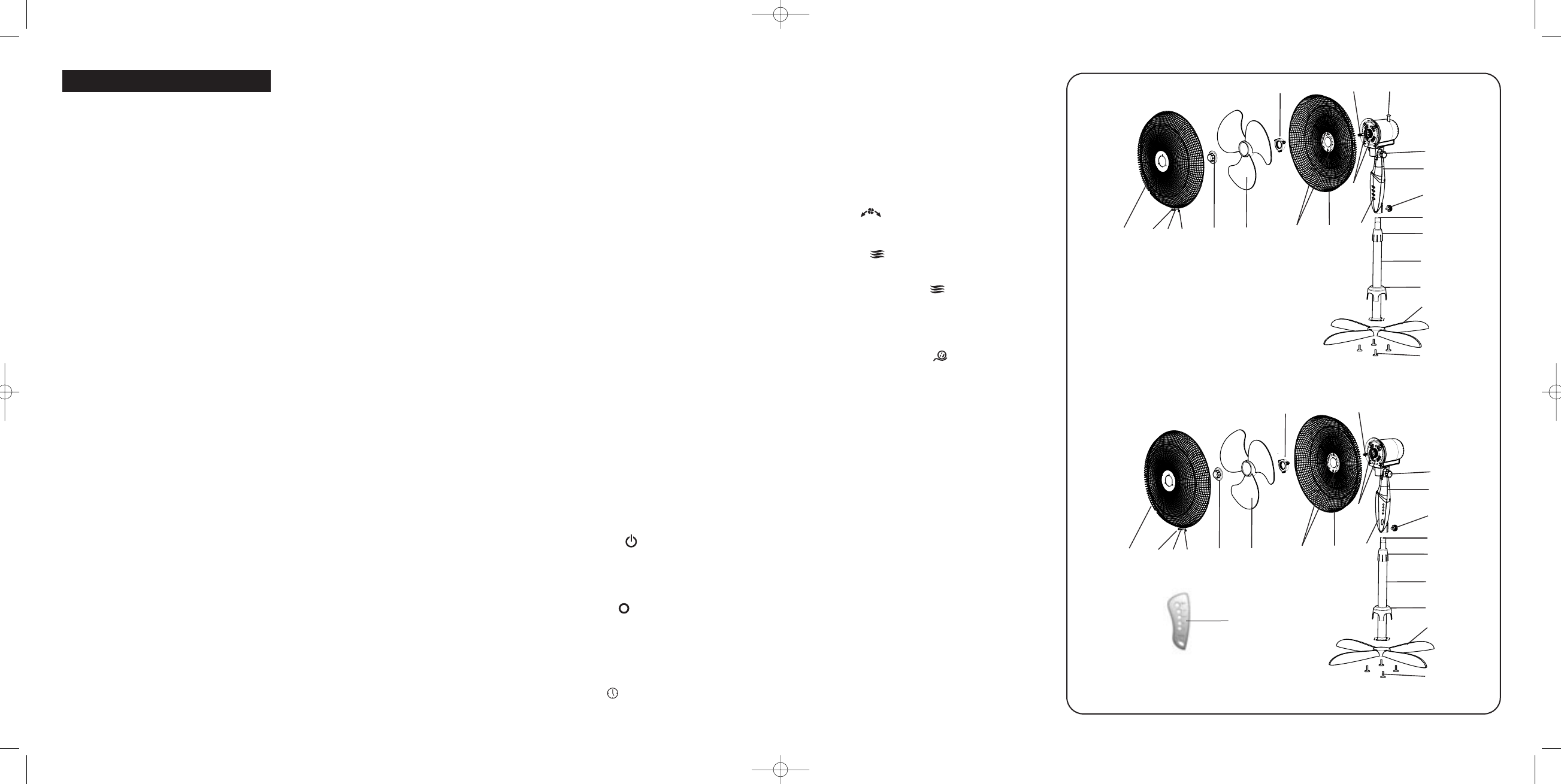
ASSEMBLY INSTRUCTIONS
(See Fig. 1 and 2)
Base and pole
1. Slide the main pole (A) on the cross base
(B), making sure the alignment of four holes.
Then use four cross base screws (C) to lock
them together.
2. Slide the stand base sheath (D) into the
main pole.
3. Unscrew the pole extension screw (E)
around the top of the main pole and raise
the chrome extension pole (F) to its full
height. Retighten the pole extension screw.
4. Take the fan head assembly (G), slacken
the fixing screw (H) and insert the neck of
the fan head assembly onto the pole.
Retighten the fixing screw.
Head and guard
5. Unscrew the fan blade securing screw (I).
NOTE: THIS SCREW HAS LEFT HANDED
THREAD AND THEREFORE IS REMOVED
BY TURNING CLOCKWISE. Unscrew the
rear grill mounting nut (J).
6. Position the rear grill (K) over the motor
shaft (L) making sure the notches (M), 2 at
the top and 1 at the bottom of the rear grill,
fit over the corresponding prongs (N) on the
motor housing.
7. Please make sure the rear grill fits securely
against the motor housing before securing
the rear grill in its place using the rear grill
mounting nut (J). Turn this nut clockwise
and tighten firmly.
8. Slide the fan blade (O) with the hollowed
interior of the blade facing toward the rear
grill, firmly onto the motor shaft. The top of
the motor shaft should lie even with the
centre of the fan blade.
9. Now use the securing screw (I) to lock the
blade into place. NOTE: THIS SCREW
HAS A LEFT HANDED THREAD AND
THEREFORE TIGHTENS
ANTICLOCKWISE. Ensure the screw is tight
but do not overtighten.
10. Centre the front grill (P) by aligning the
Bionaire logo on the logo plate so that it is
horizontal and parallel with the floor. Then,
holding the front grill against the rear grill,
hook the top of the grill ring over the to of
the rear grill. Gently push the two parts of
the grill together until the clips around the
U.K. and IRELAND
BASF17V
Fig. 1
Q
P
I
O
K
J
N
U
G
H
F
E
D
B
C
W
L
T
M
S
R
A
BASF17VRC
Fig. 2
Q
P
I
O
K
J
N
U
G
H
F
E
D
B
C
W
L
M
S
R
A
V
BASF17V/17VRCIUK04EM1.qxd 12/10/04 09:21 Page 4