


4
(F) Fan Starter: Although not normally considered a
safety device, the fan starter is wired so that its 13-14
interlock powers the control system. Thus the main fan
must be energized before the gas system can be pow-
ered. This provides one more assurance, in addition to
the Airflow Switch, that the fan is operating before heat
comes on.
(G) Secondary Safety** and Bleed Valves (or “Block &
V ent Valves): A second main line gas valve is inst alled
downstream of the primary safety valve. A vent line with
an electrically operated normally-open valve takes off lat-
erally between the two main line valves. This vent line
must be piped to atmosphere outside the building, by the
customer on installation (See Suggestions for Regulator.)
IX. OPERATION
X. MAINTENANCE
(Note: See wiring diagram for part number and manufacturer
of any control component. See manufacturer’s instruction
sheets for more information.)
(A) Fan Motor Bearings: Refer to green sheet on mainte-
nance of direct-connected fans. Most fan motors have a
1/8" NPT pipe at each bearing, which may be removed
for lubrication, in the event lube tubes were not factory-
installed.
(B) Burner: Side plates and their air holes should be
checked periodically, to be sure these parts are not fouled
or plugged.
(C) Burner Adjustment: (See Operation).
(D) Fireye: The UVM-IF utilizes solid state components.
The only required maintenance is on its external compo-
nents; i.e., the Flame Rod and the Ultra -Violet Scanner.
See “Maintenance” in manufacturer’s bulletin C-400.
(E) Scanner: Remove scanner occasionally, clean lens,
and be sure that mounting pipe nipple is clear of insects
and dirt.
(F) Spark Ignitor: Ignition takes place by means of a spark
jumping from the ignitor to the side plate of the burner.
The spark gap should be 1/8" to 3/16" (. 12" -. 19"), and
located downstream of an air mixing hole, so that there is
a gas-air mixture to be ignited. Check for carbon “bridge”
between electrode and burner which may short out spark
and prevent ignition.
XI. TROUBLESHOOTING
First check for loose wiring connections.
Then check the following for specific symptom:
(A) Fan Won’t Start -
(1) Selector in “OFF” position.
(2) Check 3-phase line leads for power across all 3
phases, if one line is dead, check fuses or breaker in
main disconnect.
(3) Check fuse on control circuit transformer.
(4) Try “SUM” setting. If fan runs, but won’t run on “@”,
check 1T’HS outdoor thermostat (if used) for open R-B
contact; check limit switch on door for open-contact.
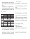
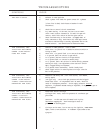
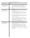
(A) Gas Adjustment: Heat output is adjusted by varying
the outlet pressure of the regulator (see Gas Pressure
Regulator). A pressure gage may be attached to the pip-
ing at a leak-test connection. Table 1 shows performance
at various inlet pressures.
(B) Pilot Adjustment: This heater is equipped with inter-
rupted pilot; i.e., after main burner ignites, pilot is cut off.
Scanner then senses main flame only. Pilot flame was
properly adjusted at the factory. Field adjustment is pos-
sible by removing the protective cap and using a screw-
driver with a small bit.
GAS
SUPPLY
PRESSURE
(in. w.g.)
MODEL B-22, 6500 CFM
5” 700 99 169
6” 765 109 179
7” 820 117 187
8” 7” MAX. RECOMMENDED
1000’S
BTU/HR
RISE
(º F)
FINAL TEMP.
(º F)*
GAS
SUPPLY
PRESSURE
(in. w.g.)
MODEL B-24, 7900 CFM
5” 790 92 162
6” 865 101 171
7” 930 109 179
8” 990 116 186
1000’S
BTU/HR
RISE
(º F)
FINAL TEMP.
(º F)*
* Based on 70º F. inlet temperature.