


5 EUROLIGHT LD6230 Installation Instructions
◊ Please make sure that each dimmer load is connected to a separate
channel. Never connect more than one output to just one common
neutral conductor.
◊ ATTENTION: Due to electrocution danger, do not use your dimmer pack
if there are bare cables visible.
Connection Options for Flexible Usage
Output Connector (HARTING)
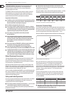
In the back of your LD6230 there is a cable bushing for connecting your
illuminants. Open the ap on the top of the LD6230 to get to the terminal clamps
used for this purpose. Here you have the option to retrot a 16-pin HARTING
connector. To do that, you rst have to remove the back-bearing cover sheet and
connect the HARTING connector to the terminal clamps.
PIN assignment/HARTING connector
PIN 1 Phase channel 1 E1 PIN 9 Neutral channel 1 N
PIN 2 Phase channel 2 E2 PIN 10 Neutral channel 2 N
PIN 3 Phase channel 3 E3 PIN 11 Neutral channel 3 N
PIN 4 Phase channel 4 E4 PIN 12 Neutral channel 4 N
PIN 5 Phase channel 5 E5 PIN 13 Neutral channel 5 N
PIN 6 Phase channel 6 E6 PIN 14 Neutral channel 6 N
PIN 7 free – PIN 15 free –
PIN 8 free – PIN 16 free –
Ground wires need to be fastened to their respective PE connectors
CEE Power Supply Connector
Also located in the back is a cable bushing for the mains supply. Here, you can
retrot a 5-pin CEE 32 A mains connector by removing the back-bearing cover
sheet and connect the CEE high-voltage connector to the connecting terminal.
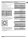
The following illustration shows how the connections are allocated:
L3 L2
N L1
CEE connector pin allocation
◊ Removable mains connector cables with mains interconnections
(pursuant IEC60320) must match the minimal load-carrying capacity
of the connector or must comply with the IEC60799 standard.
The interconnection and the cable must comply with prevalent
nominal values (maximal voltage and current).
◊ During the installation, please adhere to the instructions provided by
the connector manufacturer.
Specications
Channels
Number 6
Load per channel 0.2 A min./10 A max.
Maximal load per channel 10 A using a 3-phase connector
Frequency 50/60 Hz
Inputs
Power supply 3-phase connector, internal
terminalblock/PG cable screw joint,
CEEconnector(optionalinstallation by
qualied personnel)
Analog 0 to +10 V via 8 pin DIN
Digital DMX512 via XLR 5 pin
Outputs
Digital DMX512 via XLR 5 pin
Load Internal terminal block/PG cable screw
joint, HARTING
®
(optional installation by
qualiedpersonnel)
System Fuses
Load securing per channel 10 A cable protection switch (type C)
Control section fuse 2 x T 100 mA H/250 V 1 x T 160 mA
H/250 V for voltage range 220 - 230 V
(EU) 2 x T 160 mA H/250 V 1 x T 315 mA
H/250 V for voltage range 120 V (UL)
Power Supply
Voltage
USA/Canada 120 V~, 60 Hz
Europe/U.K./Australia 240 V~, 50 Hz
Maximum power consumption 3 x 20 A
Dimensions/Weight
Dimensions (H x W x D) approx. 3 ⁄ x 19 x 15 ⁄"
approx. 84.3 x 482.6 x 403.8 mm
Weight approx. 21.6 lbs / 9.80 kg
BEHRINGER continuously strives to assure the highest quality standards possible. Required modifications may
be implemented without prior notice. Technical data and the appearance of the unit may deviate from the above
values and/or illustrations.