


22 EUROLIGHT LC2412 User Manual
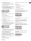
9.3.2 Sub D connections (Analog Control)
The following table shows the cable layout of the individual contacts of the sub D
connection for analog dimmer control.
Pin No. Cons. channel
Pin 1 Channel 1
Pin 2 Channel 2
Pin 3 Channel 3
Pin 4 Channel 4
Pin 5 Channel 5
Pin 6 Channel 6
Pin 7 Channel 7
Pin 8 Channel 8
Pin 9 Channel 9
Pin 10 Channel 10
Pin 11 Channel 11
Pin 12 Channel 12
Pin 13 Special 1
Pin 14 Special 2
Pin 15 Ground
Table. 9.1: Cable layout of the sub D connection
9.3.3 MIDI connection
Coonect to other MIDI equipment or another EUROLIGHT LC2412 by using
common MIDI cables. The cables should never be longer than 15 m (45 ft).
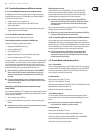
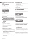
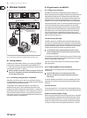
9.3.4 Audio connections
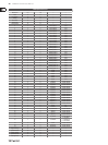
To control the EUROLIGHT LC2412 via an audio signal, please use a mono jack
connector with standard conguration.
strain relief clamp
sleeve
tip
sleeve
(ground/shield)
Unbalanced ¼" TS connector
tip
(signal)
Fig. 9.2: ¼" TS connector for audio signals
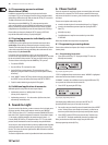
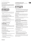
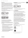
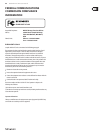
9.3.5 Footswitch
You can use a footswitch to trigger chase steps. This way, both of your hands
remain free, letting you control additional settings of your LC2412.
strain relief clamp
sleeve
tip
sleeve
pole 1/ground
tip
pole 2
The footswitch connects both poles momentarily
¼" TS footswitch connector
Fig. 9.3: Footswitch connector
As long as a footswitch is kept pressed, the connection of both contacts is closed.
Therefore, a footswitch does not act as a switch.
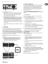
9.4 Rack mounting
Your EUROLIGHT LC2412 is factory-equipped with rack-mounting brackets.
Youcan screw these on to the side of your LC2412 on a per-need basis.
◊ Always make sure that your LC2412 is provided with sufficient
ventilation to avoid overheating of the unit!