


ModelSF
Chassis Plan
. Reduces Investment Up To 65%
. Reduces Storage Space Up To 85%
. Speeds Service Calls
The Beckett Chassis Plan lets you stock a minimum
number of oil burners and still get maximum installation
flexibility. The chassis represents up to 90% of the total
burner cost, but a single chassis adapts to all firing rates
commonly encountered in upgrading and replacement jobs.
To a minimum chassis stock, you add an assortment of air
tube combinations. From this assortment, you can choose
the precise combination for your application requirements.
To complete the installation, simply install the proper
support.
OIL BURNER
How To Order
Order Burner Chassis
1. Model SF Burner Chassis
2. Type of Fuel Unit (single or two-stage)
3. Primary control
~
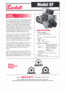
A ONE-PIECE FLAME RETENTION HEAD
The highly stable flame and the intense combustion increases fuel
efficiency as much as 35%.
B STURDY DIE-CAST ALUMINUM HOUSING
The precisely machined, die cast aluminum housing aligns the
pump and motor for smooth operation and long coupling life.
C NOZZLE LINE ELECTRODE ASSEMBLY
Self-centering design delivers oil to the nozzle and high voltage
electricity to the electrodes. Air flow to the head is controlled and
evened out by a static plate for smooth, efficient combustion.
D DRIVE MOTOR
A continuous duty, split phase motor is built for daily hard use and
years of trouble free operation. Overload protection standard.
E IGNITION TRANSFORMER
10,000 volts and 23 milliamps positively and smoothly ignite the
fuel. No TV interference. Designed for heavy duty continuous
operation.
Order Air Tube Combination
1. Air Tube Length (dimension A) and Firing Rate
OR
Air Tube Combination Code (see table at right)
Order Accessories
1. Specify type of supports required.
2. Add any other items such as spare parts, related
controls, valves, etc.
F SOLENOID VALVE
Provides rapid oil cutoff at the end of heat call. This reduces
smoke and contributes to quieter, smoother operation.
G CONNECTOR TUBE FITTING
A high quality flare fitting standard with Beckett.
~
Model SF Air Tube Combination Codes
Fully Approved
Listed by Underwriters' Laboratories, Inc.
Accepted by New York City M.E.A.
Approved by Commonwealth of Massachusetts
C.S.A. Certified
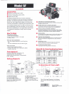
Optional Supports
1/4'
No. 5685 Pedestal Support
For conversion applications.
No mounting flange is required.
Note: Part No. 5606 Extended Pedestal
Support is also available, and provides
elevation from 8-114" to 13".
PEDESTAL
SUPPORT
KIT
EXTENDED
PEDESTAL
KIT
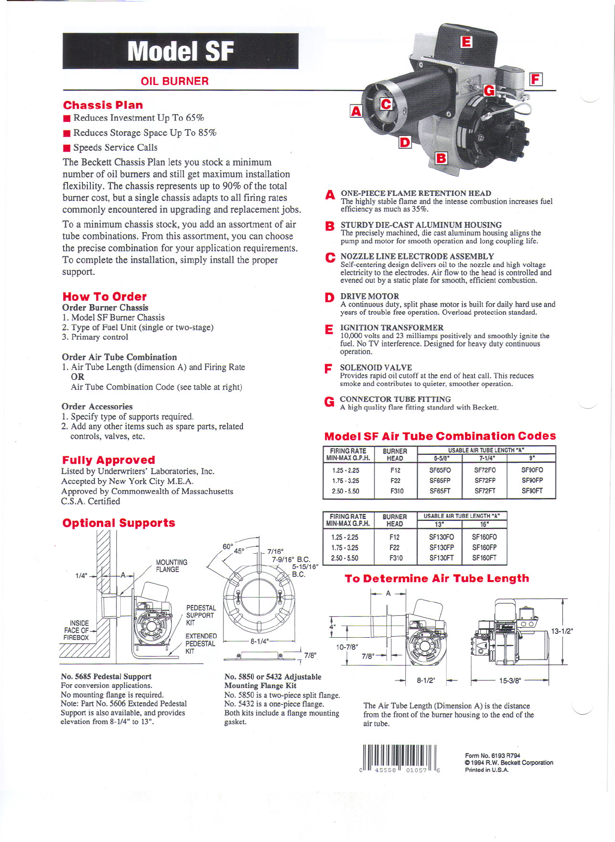
To Determine Air Tube Length
,;1
8-1/4'
l
~- 7/8',
I
No, 5850 or 5432 Adjustable
Mounting Flange Kit
No. 5850 is a two-piece split flange.
No. 5432 is a one-piece flange.
Both kits include a flange mounting
gasket.
eI
The Air Tube Length (Dimension A) is the distance
from the front of the burner housing to the end of the
air tube.
~
JIII~!IJll!llIll!tl!IJlllllt
Form No. 6193 R794
'01994 R.W. Beckett Corporation
Printed in U.S.A.
FIRINGRATE
BURNER
USABLEAIRTUBELENGTH"A"
MIN-MAXG.P.H. HEAD
6-5/8'
7-1/4' g'
1.25-2.25
F12
SF65FO
SF72FO SF90FO
1.75-3.25 F22 SF65FP SF72FP SF90FP
2.50-5.50
F310 SF65FT SF72FT
SF90FT
FIRINGRATE
BURNER
USABLEAIRTUBELENGTH"A"
MIN-MAXG.P.H.
HEAD
13' 16'
1.25-2.25 F12
SFI30FO SF160FO
1.75-3.25 F22 SF130FP
SFI60FP
2.50-5.50 F310
SFI30FT SF160FT