


Beckett
Instruction Manual – Model AF Oil Burne
r
Pipe, wire, & adjust burne
r
Connect fuel lines
(continued)
Mount burner on appliance
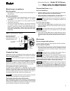
Fuel line installation –
Mounting options
• Continuous lengths of heavy wall copper tubing are recommended.
Always use flare fittings. Never use compression fittings.
•
Bolt the burner to the appliance using the factory-mounted flange or an
adjustable flange.
• Always install fittings in accessible locations. Fuel lines should not run
against the appliance or the ceiling joists (to avoid vibration noise).
Mounting dimensions
• When using the Beckett universal adjustable flange, mount the air tube at
a 2° downward pitch unless otherwise specified by the appliance
manufacturer.
Never
use Teflon tape on any fuel fitting. Tape fragments can
lodge in fuel line components and fuel unit, damaging the equipment and
preventing proper operation.
WARNING
•
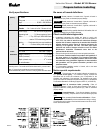
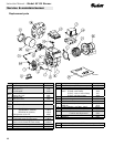
Verify that the air tube installed on the burner provides the correct
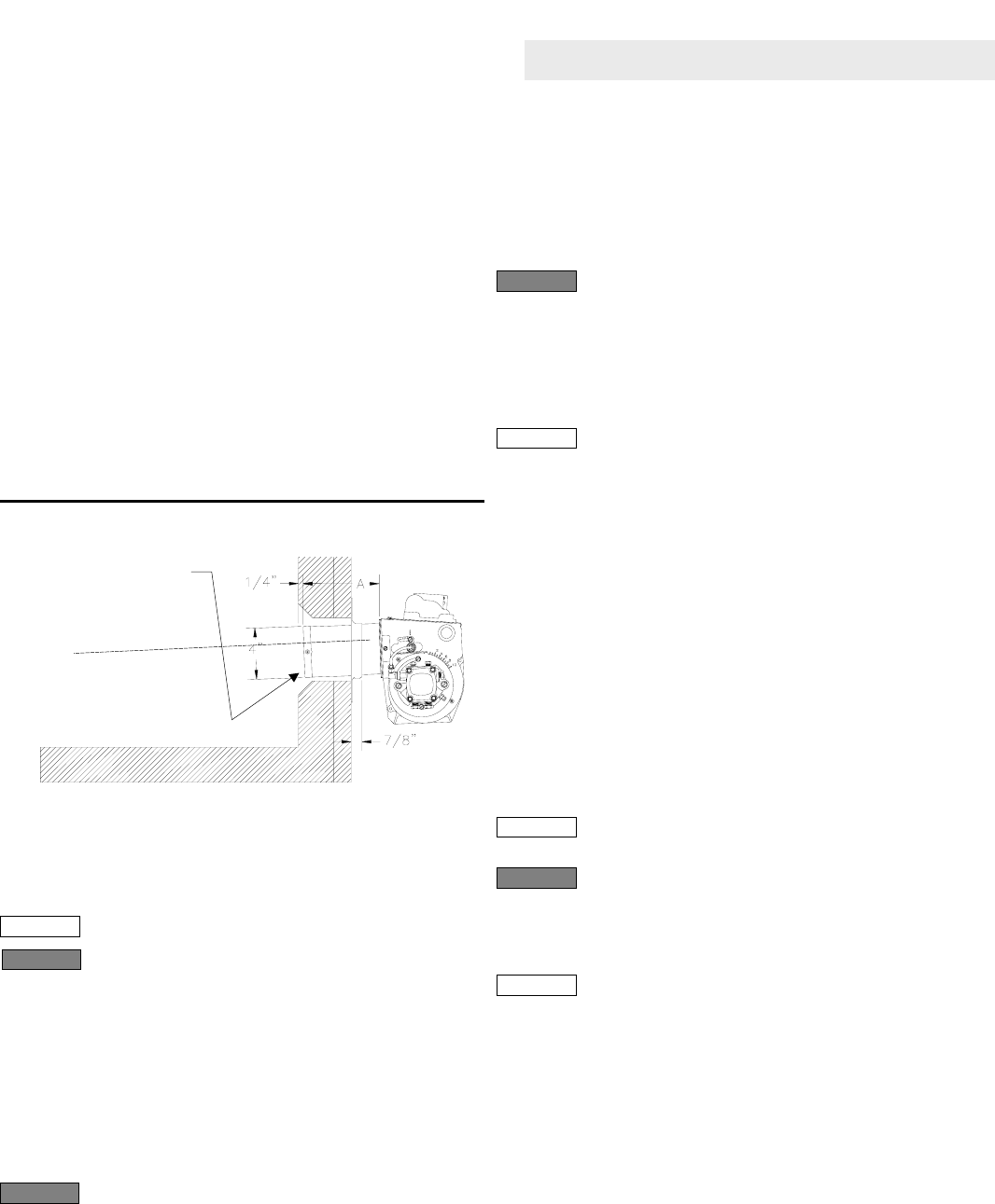
insertion depth. See Figure 3.
Fuel line valve and filter –
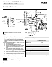
• The end of the air tube should normally be ¼" back from the inside wall of
the combustion chamber. Never allow the leading edge of the head
assembly to extend into the chamber, unless otherwise specified by the
heating appliance manufacturer. Carefully measure the insertion depth
when using an adjustable flange. Verify the insertion depth when using a
welded flange.
•
Install two high quality shutoff valves in accessible locations on the oil
supply line. Locate one close to the tank and the other close to the burner,
upstream of the filter.
Some states require these valves to be fusible-handle design
for protection in the event of fire. We recommend this as good industry
practice for all installations.
NOTICE
•
Install a generous capacity
filter
inside the building between the fuel tank
shutoff valve and the burner, locating both the filter and the valve close to
the burner for ease of servicing. Filter should be rated for 50 microns or
less.
Figure 3
– Mounting burner in appliance
Tilt down 2
°
Pack burner opening with
ceramic fiber refractory if
space between burner air tube
and opening exceeds ½ inch.
SK8745
Wire burner
Burner packaged with appliance
• Refer to appliance manufacturer’s wiring diagram for electrical connections.
Burner applied at jobsite
•
Refer to Figures 4 and 5, page 8, for typical burner wiring, showing cad
cell primary controls. Burner wiring may vary, depending on primary
control actually used. The oil valve shown in Figures 4 and 5 may be an
optional feature.
Connect fuel lines
All wiring must be in accordance with the latest revision of
National Electric Code NFPA 70 and local codes and regulations.
NOTICE
Carefully follow the fuel unit manufacturer’s literature and the latest edition of
NFPA 31 for oil supply system specifications. If this information is unavailable,
use the following basic guidelines..
The wiring diagrams in this manual are for general reference
only
, and apply only to burners equipped with R8184G or R7184 primary
controls. For other controls, refer to the control manufacturer’s literature or the
diagrams supplied with the appliance. Failure to apply correct wiring could
result in severe personal injury, death or substantial property damage.
WARNING
Fuel units with automatic bypass do not require a bypass plug.
NOTICE
The burner fuel unit is shipped without the bypass plug installed.
You must install this plug on two-pipe oil systems.
DO NOT
install the plug in
the fuel unit if connected to a one-pipe oil system. Failure to comply could
cause fuel unit seal failure, oil leakage and potential fire and injury hazard.
WARNING
The R7184 primary control with valve-on delay (prepurge) and
burner motor-off delay (postpurge), shown in Figure 5, page 8, requires a
constant 120 VAC power source supplied to the BLACK wire on the control.
The RED wire goes to the appliance limit circuit. Please note that other control
manufacturers may use different wire colors for power and limit connections.
NOTICE
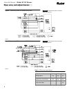
Fuel supply level with or above burner –
The burner may be equipped with a single-stage fuel unit for these
installations. Connect the fuel supply to the burner with a single supply line if
you want a one-pipe system (making sure the bypass plug is NOT installed in
the fuel unit.) Manual venting of the fuel unit is required on initial start-up. If
connecting a two-pipe fuel supply, install the fuel unit bypass plug.
The oil supply inlet pressure to the fuel unit cannot exceed 3
psi. Install a pressure-limiting device in accordance with NFPA 31.
WARNING
Fuel supply below the level of the burner –
When the fuel supply is below the level of the burner, a two-pipe fuel supply
system is required. Depending on the fuel line diameter and horizontal and
vertical length, the installation may also require a two-stage pump. Consult the
fuel unit manufacturer's literature for lift and vacuum capability.
7