


Page 8 RWB 6104 BAFG R02
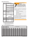
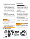
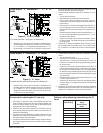
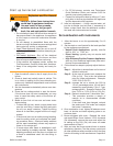
Check/Adjust ‘Z’ Dimension - ‘F’ heads
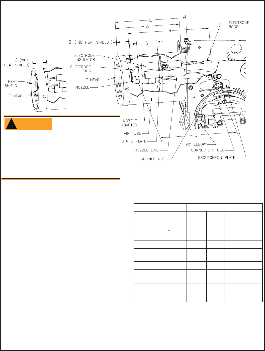
1. The important ‘Z’ dimension is the distance from the face of the nozzle
to the fl at face of the head (or heat shield, if applicable). This dis-
tance for F heads is 1-⅛” (1-⅜” if the air tube has a heat shield). The
“Z” dimension is factory set for burners shipped with the air tube in-
stalled. Even if factory set, verify that the “Z” dimension has not been
changed.
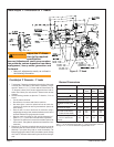
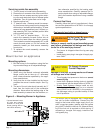
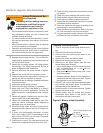
2. Use the following procedure to adjust the “Z” dimension, if it is not
correct:
Turn off power to the burner.
Disconnect the oil connector tube from the nozzle line
See above fi gure. Loosen the splined nut from the nozzle line.
Loosen the hex head screw securing the escutcheon plate to the
burner housing.
Place the end of a ruler at the face of the nozzle and, using a
straight edge across the head, measure the distance to the face of
the head. A Beckett T501 gauge may also be used.
Slide the nozzle line forward or back until this dimension for F
heads is 1-⅛” (1-⅜” to the face of the heat shield, if applicable).
Tighten the hex head screw to secure the escutcheon plate to the
burner chassis. Then tighten the splined nut and attach the oil con-
nector tube.
3. Recheck the “Z” dimension periodically when servicing to ensure the
escutcheon plate has not been moved. You will need to reset the “Z”
dimension if you replace the air tube or nozzle line assembly. The
Beckett Z gauge (part number Z-2000) is available to permit checking
the F head “Z” dimension without removing the burner from the appli-
ance.
y
y
y
y
y
y
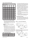
Check/Adjust ‘Z’ Dimension for ‘F’ Heads
For usable length A (inches)
Dimension (inches)
F Head L1
Head
L2
Head
V1
Head
H (nozzle to head), +
1/32
N/A
1/4 7/32 1/4
L (Total tube length)
A+
1/2 A+1/2 A+1/2 A+1/2
R (electrode length), + 1/4
A+2-1/4 A+1-1/8 A+1-1/8 A+1-1/8
S (adapter to static plate), +
1/16
(Note 1) 1-3/8 1-3/8 1-3/8
Q (nozzle line length),
A+
15/16 A+ 3/16 A+ 3/16 A+ 3/16
Z (F head-no heat shield)
(F head-with heat shield)
1-
1/8
1-3/8
N/A
N/A
N/A
N/A
N/A
N/A
Z (L1 head w/straightshroud)
(L1/L2/V1 head w/conic
shroud)
N/A
N/A
1-
3/8
1-3/4
N/A
1-3/4
N/A
1-3/4
Note 1: 1-3/8 for dimension A less than 4”; 1-5/8 for dimension A from 4”
through 4-
1/2 “, 2-13/32 for dimension A greater than 4-1/2”.
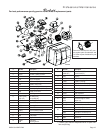
Burner Dimensions
Make all adjustments exactly as outlined in
the following information.
y
Incorrect Adjustments could cause combus-
tion problems, carbon deposition from fl ame
impingement, heavy smoke generation and
fi re hazard.
WARNING
!
Adjust the ‘Z’ dimen-
sion to the required
specifi cation.
Figure 3. ‘F’ Head