


Instruction Manual – Model AFII Oil Burner
Beckett
Inspect/prepare installation site Inspect/prepare installation site
(continued)
Exhaust fans and other air-using devices
Chimney or vent
• Inspect the chimney or vent, making sure it is properly sized and in good
condition for use.
Size air openings large enough to allow for all air-using devices in addition
to the minimum area required for combustion air. If there is any possibility
of the equipment room developing negative pressure (because of exhaust
fans or clothes dryers, for example), pipe combustion air directly to the
burner.
•
For those installations not requiring a chimney, such as through-the-wall
vented appliances, follow the instructions given by the appliance and
power venter (if used) manufacturers.
Direct air supply and sidewall venting
Clearances to burner and appliance
• When sidewall venting appliances, carefully follow appliance and power
venter instructions for installation and wiring.
• Provide space around burner and appliance for easy service and
maintenance.
• AFII burners are equipped with a removable air inlet to allow use of a 4”
duct to supply outside air for combustion. Do not exceed 70 equivalent
feet. Allow 6 feet for each elbow.
• Check minimum clearances against those shown by the appliance
manufacturer and by applicable building codes.
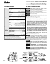
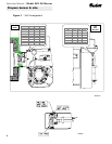
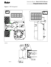
1. Remove the inlet cover.
2. Insert 4" duct into the inlet ring.
3. Fasten duct into place using at least 3 sheet metal screws evenly
spaced around the inlet ring. Refer to Figure 1.
Combustion chamber — Burner retrofitting
4. Remove the barometric draft control unless it is in the same
atmospheric pressure zone as the inlet.
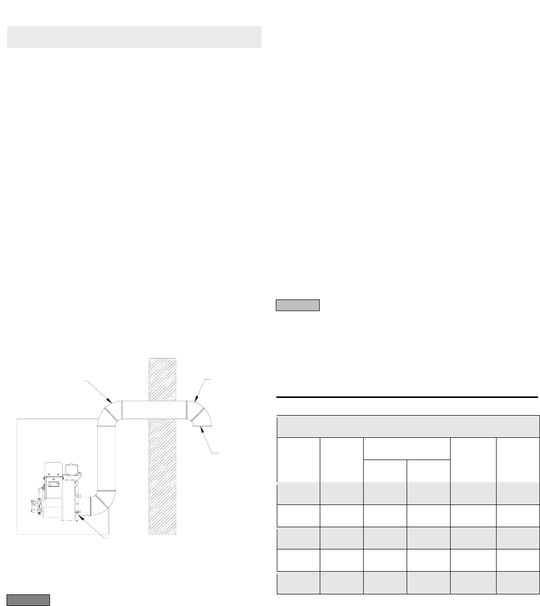
On the outside of the home use a 90° elbow pointed downward with a 1/4"
mesh screen over its opening. The air inlet elbow must be located above
the snow line and in such a way as to prevent leaves and/or other debris
from blocking the air flow. Such debris will prevent proper operation of the
burner. Refer to local codes for proper location of inlet.
Figure 1
– Outside air connection
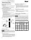
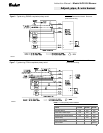
Verify that the appliance combustion chamber provides at least the minimum
dimensions given in Table 2.
When retrofitting an appliance that has an unlined stainless
steel combustion chamber, chamber burnout could result from the use of a
high performance burner. Protect the chamber from high temperatures
through the use of "wet-pac" or a similar ceramic liner. Some equipment may
utilize a stainless steel combustion chamber that has been designed and
tested by the manufacturer for use with a flame retention burner, therefore
ceramic protection would not be necessary. Refer to appliance manufacturer’s
instructions. Failure to comply could result in damage to heating equipment.
Table 2
– Minimum combustion chamber dimensions
Combustion air supply
See NFPA Standard 31 for complete details.
If the burner is not supplied with a reliable combustion air
source, the burner cannot properly burn the fuel. This would result in
incomplete combustion, causing sooting and possible emission of carbon
monoxide. Severe personal injury, death or substantial property damage could
occur.
Chamber dimension (inches)
Rectangular
Firing
rate
(gph)
Round
I.D.
Width Length
Height
Floor to
nozzle
0.50
8 7 8 12 5-6
0.75
9 8 9 12 5-6
1.00
10 9 10 12 ½ 5-6
1.25
11 10 11 12 ½ 5-6
1.50
12 11 12 13 6-7
INLET
RING
4 IN. DUCT
¼” MESH
SCREEN
AIR
INLET
ELBOW
SK8810
CAUTION
WARNING
Prepare burner & site
Appliance located in confined space
The confined space should have two (2) permanent openings: one near
the top of the enclosure and one near the bottom of the enclosure. Each
opening shall have a free area of not less than (1) one square inch per
1,000 BTU’s per hour of the total input rating of all appliances within the
enclosure. The openings shall have free access to the building interior,
which should have adequate infiltration from the outside.
4