


6 Troubleshooting
5 Power ON
Page 2 of 2 75.5179.05 20080415
Upon powering, observe the back of the beams for LED indications.
There should be a green LED illuminated at the back-side of the
Emitter and the Receiver to indicate power ON. The Receiver
should also have an orange LED illuminated when the beam is
aligned and unobstructed.
Additionally, the SBK30 Interface LED also has indications of its
own, depending on the switch selection and SBK30 beam status.
8 Company Contact
Do not leave problems unresolved. If a satisfactory solution cannot be achieved after troubleshooting a problem,
please call BEA, Inc. If you must wait for the following workday to call BEA, leave the door inoperable until satisfactory
repairs can be made. Never sacrifi ce the safe operation of the automatic door or gate for an incomplete solution.
The following numbers can be called 24 hours a day, 7 days a week. For more information, visit www.beasensors.com.
US and Canada:
Canada:
Northeast:
1-866-249-7937
1-866-836-1863
1-866-836-1863
Southeast:
Midwest:
West:
1-800-407-4545
1-888-308-8843
1-888-419-2564
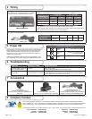
7 Accessories
Jamb Cap Kit
(included with SBK30 beam set)
May be used on sliding door applications or
otherwise
Rail Mount Kit
(included with SBK30 beam set)
Used on 1.75” x 0.5” barstock-type guide rails.
InterFace Board (IFB)
(included with SBK30 beam set)
Converts an NPN output to a dry relay output
capable of powering one SBK30 Beam pair.
SYMPTONS PROBABLE CAUSES CORRECTIVE ACTION
No LED’s visible at the back
side of the beam heads
No Power. Check power supply.
Check for damaged cabling and connection points.
Beam output will not
change state
Beams are misaligned.
Faulty transmitter or receiver.
Check for yellow LED at receiver to confi rm alignment. If an orange LED
can’t be obtained and green LED’s are on at TX and RX, replace receiver.
If green LED is off at TX, replace TX beam head.
SBK30 BACK-SIDE LED DISPLAY
GREEN
LED
ON = Power is applied
YELLOW
LED
ON=Beams are unobstructed
OFF=Beam Broken
RED
LED
N/A
If using a BEA LO-Linx lockout module, simply plug
each beam into the connection point at the module.
Connection points are identifi ed on the LO-Linx.
If using SBK30 beams directly, be sure the NPN/Light Operate output works with the door
controller. The chart below shows wire color designations for the SBK-30 TX / RX:
DESCRIPTION
TX / EMITTER RX / RECEIVER
CABLE TX BEAM CABLE RX BEAM
Ground Black Blue Black Blue
NPN/Light Operate* White N/A White Black
10 to 30 VDC Red Brown Red Brown
*Light operate means ground is provided when receiver ‘sees’ emitter.
To wire directly to door control, cut off connector on extension cable and strip jacket from
wires. Connect wires according to door control guidelines.
If the application requires a dry output, the SBK-30 IFB can be used. Simply plug one beam set into the IFB and wire the appropriate relay outputs
(NO or NC) per the application.
SBK-30 IFB
4 Wiring
SBK-30 Connection
SBK-30 INTERFACE Red Black White Green Brown
DESCRIPTION
+ 12 - 24
VAC/DC
- 12 - 24
V
AC/DC
COM NO NC