


75.5351.02 EN 20080317 (75.5350) Page 2 of 7
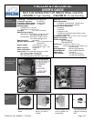
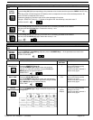
To remove or to
insert the cable:
• Unscrew the retaining
nut;
• Pass the cable through
the grommet and the
retaining nut.
• Tighten the retaining nut.
Opening the sensor Closing the sensor
• Loosen the retaining nut
until the cable slides easily into the
grommet;
• Partially unscrew the 2 front cover
screws;
• Pull out the front cover with the 2
front cover screws.
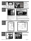
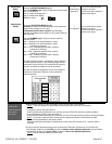
• Connect the quick disconnect terminal block to the main
electronic circuit;
• Slide the main electronic circuit into the 2 housing slot
guides;
• Gently push the front cover and make sure that the external
housing is properly seated (front cover must be flush with
housing).
• Screw the 2 front cover screws and tighten the retaining nut.
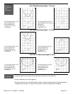
Ceiling Mounting Wall Mounting
Remark: The bold-type values give the minimum distance required to be able to fully adjust the sensor.
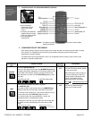
• Check that both locking collar
are at the same angle;
• Align the bracket slot to the
locking collar guide as shown.
WIRING
OPENING AND
CLOSING THE
SENSOR
SENSOR
DIMENSIONS
AND
MOUNTING
2.5 in
5 in
6.25 in
6.5 in
6 in
3 in
5.5 in
6 in
5 in
6.25 in
BRACKET
MOUNTING
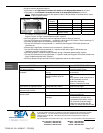
US Wire Color: Red Black White Green Yellow
12-24 VAC/DC COM NO NC
Euro
p
ean Wire Color: Brown Green White Yellow G
r
a
y