


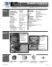
75.5268.01 20070111 Page 2 of 7
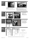
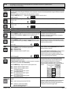
• Loosen the retaining nut until the cable slides easily into
the grommet ;
• Partially unscrew the 2 front cover screws ;
• Pull out the front cover with the 2 front cover screws.
• Connect the quick disconnect terminal block to the main electronic
circuit ;
• Slide the main electronic circuit into the 2 housing slot guides and
pull the main cable gently at the same time ;
• Gently push the front cover and make sure that the external
housing is properly seated (front cover must be flush with housing).
• Screw the 2 front cover screws and tighten the retaining nut.
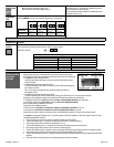
• Check that both locking
collars are at the same
position
• Align the bracket slot to the
locking collar guide as shown
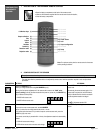
BROWN-GREEN Power supply
YELLOW COM 1
WHITE NC 1
PINK NO 1
BLACK COM 2
RED NC 2
BLUE NO 2
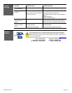
To insert or to remove the cable:
• Unscrew the retaining nut
• Pass the cable through the
retaining nut and the grommet
• Screw the retaining nut
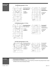
Ceiling mounting
Wall mounting
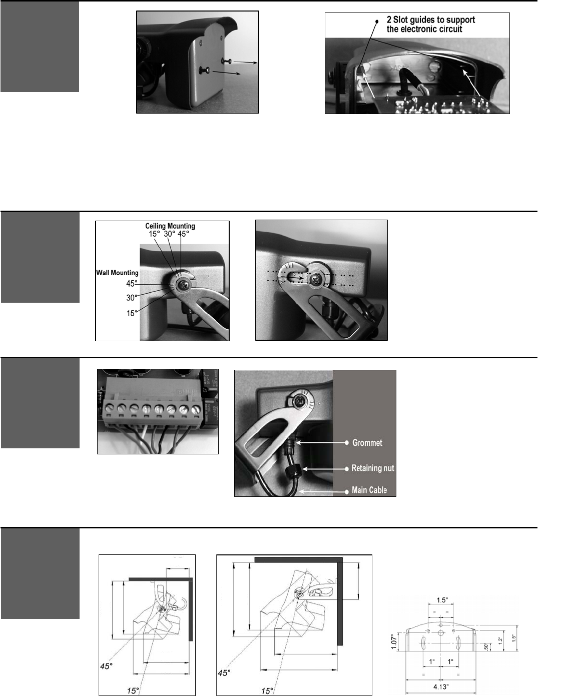
Note: The bold-type values give the minimum distance required to be able to fully adjust the sensor.
OPENING AND
CLOSING THE
SENSOR
BRACKET
MOUNTING
WIRING
SENSOR
DIMENSIONS
AND MOUNTING
Bracket dimensions
2.5 in
5 in
6.25 in
6.5 in
6 in
3 in
5.5 in
6 in
5 in
6.25 in