


75.5185.04 20070727 Page 3 of 8
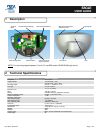
3
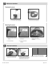
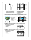
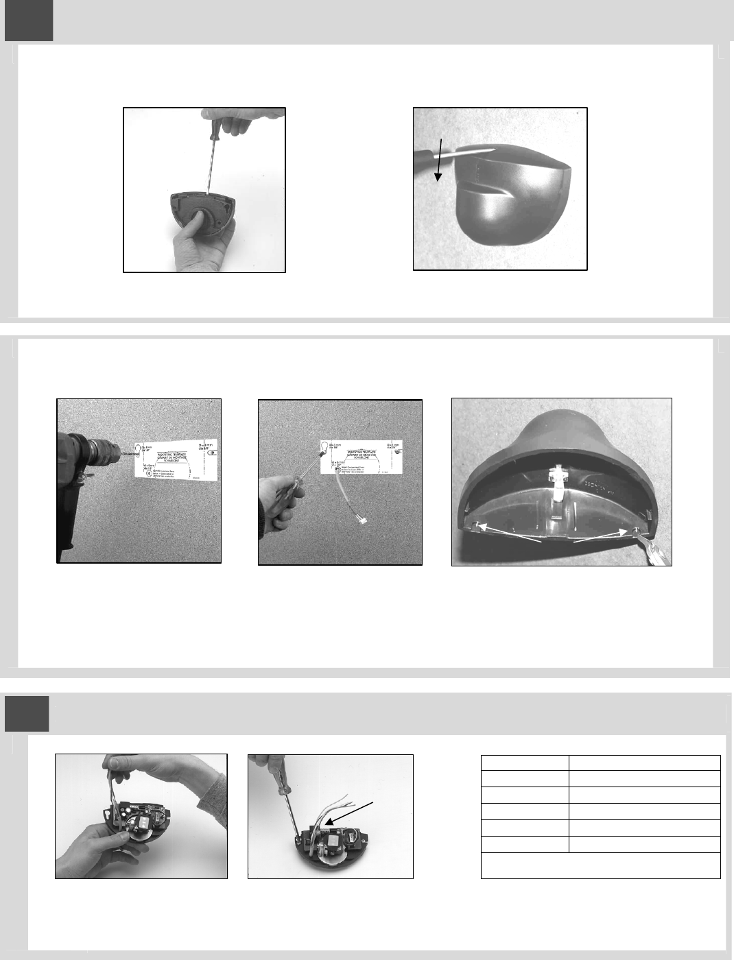
Mechanical Installation
Opening the sensor
From behind, before installation From the front, after installation
Mounting the sensor
Paste the template at desired
location.
Insert screws but do not screw
them fully in.
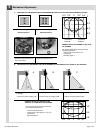
Optional cable routing:
Notch the cover as shown in
the picture.
Drill as instructed. Pass the cable where
indicated.
4
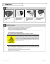
Electrical Installation
Terminal Connection
1 (Red) 12 to 24 VAC / DC (+)
2 (Black) 12 to 24 VAC / DC (-)
3 (White) Relay Common
4 (Green) Relay N.O.
5 Relay N.C.
Note: Input power tolerance is +/- 10% for
AC, and -10% to +30% for DC power.
Run the cable through the wire
passage hole just below PCB.
Position the sensor and tighten the
two screws. Make sure you leave
enough cable to reach the terminal
block near the top of the sensor.
Wiring connections are as shown above.
or