


ED810 INSTRUCTION MANUAL 27-02-07 4
INSTALLATION
Note only EDL manufactured sensors, which are suitably certified can be connected to the
ED810 and fitted in the Hazardous Area. The ED810 control unit and all uncertified
equipment should be located in the Safe Area only.
Control Unit: The unit should be mounted in a convenient position for the operator away from
possible mechanical damage or ingress of moisture and allowing the clear hinged lid to swing
open for ease of calibration etc.
Remove the front cover by unscrewing the thumb screws and then removing the hinges. Fit
mounting screws in the slots now exposed. To obtain access to the two lower slotted holes
remove the terminal cover.
Note it is not usually necessary to remove the front panel and PCB assembly during
installation or calibration.
The power supply should not allow greater than 0.25V drop along its length when carrying
1A plus current required for ancillary equipment connected. Twin core double insulated 15A
cable is normally adequate. The main DC input fuse is normally 2A rated but may be
increased to 3A allowing for ancillary equipment. External fusing may be necessary and
should be considered.
The DC supply should not deviate by more than +/- 25% of the operating voltage stated on
the serial number label. It is advisable to wire the gas detector via its own main switch so that
it may become operational without having other electrical equipment energised. Allowing a
test for gas to be made without the danger of explosion through spark ignition.
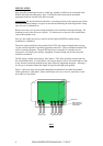
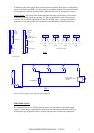
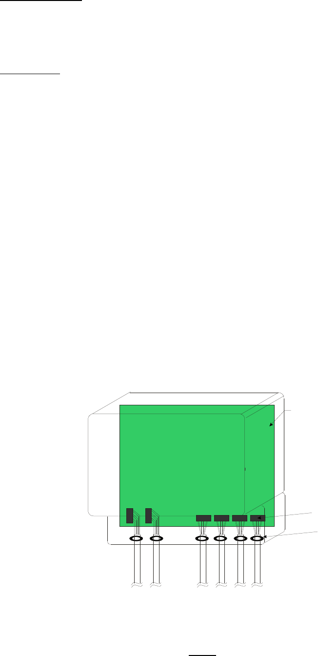
Sensor cable entry must only be made through the intended hole via either the standard
rubber grommet or cable gland. Sensor cables must not cross or lie over each other or safe
area cables see fig1 below.
FIG 1
BB PCB
TERMINAL BLOCK
RUBBER GROMMETS OR
CABLE GLAND KEEPING
CABLES SEPARATED
HAZARDOUS AREA CABLES
SAFE AREA CABLES