


Manual 2100-426
Page 7
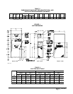
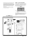
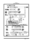
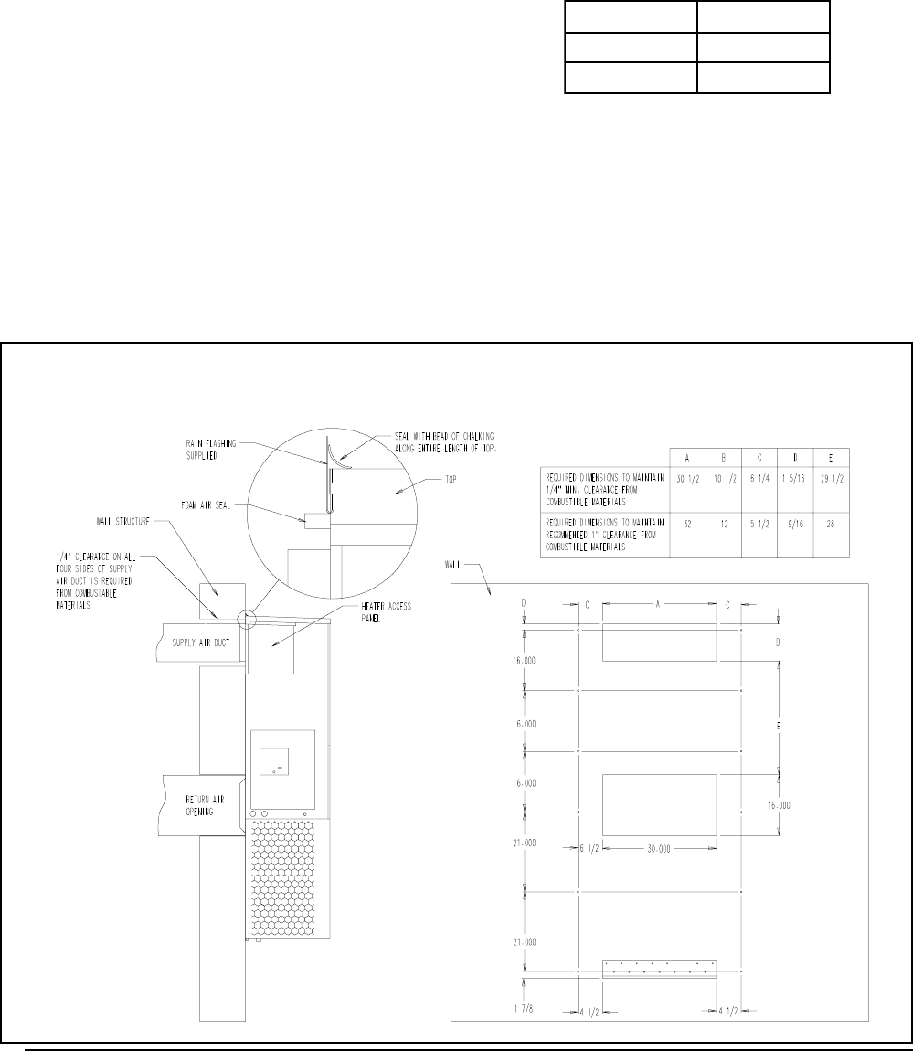
FIGURE 3
MOUNTING INSTRUCTIONS
The disconnect access door on this unit may be locked
to prevent unauthorized access to the disconnect. To
convert for the locking capability, bend the tab located
in the bottom left hand corner of the disconnect opening
under the disconnect access panel straight out. This tab
will now line up with the slot in the door. When shut, a
padlock may be placed through the hole in the tab
preventing entry.
See Start-up section for information on three phase
scroll compressor start-ups.
NOTE: The voltage should be measured at the field power
connection point in the unit and while the unit is
operating at full load (maximum amperage operating
condition).
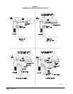
Five (5) wires should be run from thermostat subbase to
the 24V terminal board in the unit. A five conductor, 18
gauge copper, color-coded thermostat cable is
recommended. The connection points are shown in
Figure 8.
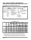
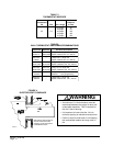
WIRING — LOW VOLTAGE WIRING
230/208V, 1 phase and 3 phase equipment dual primary
voltage transformers. All equipment leaves the factory
wired on 240V tap. For 208V operation, reconnect from
240V to 208V tap. The acceptable operating voltage
range for the 240 and 208V taps are:
TABLE 4
OPERATING VOLTAGE RANGE
PATEGNAR
V042612-352
V802781-022
MIS-1430
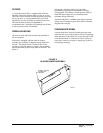
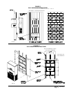
NOTE: It is recommended that a bead of silicone
caulking be placed behind the side mounting flanges
and under the top flashing at the time of installation.