


Manual 2100-400
Page 16
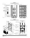
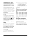
REMOVAL OF FAN SHROUD
1. Disconnect all power to the unit.
2. Remove the screws holding both grilles, one on each
side of unit, and remove grilles.
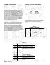
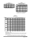
TROUBLESHOOTING
The suction line temperatures in table above are based
upon 80° F dry bulb / 67° F wet bulb (50% R.H.)
temperature and rated airflow across the evaporator
during cooling cycle.
3. Remove screws holding fan shroud to condenser
and bottom. Nine (9) screws.
4. Unwire condenser fan motor.
5. Slide complete motor, fan blade, and shroud
assembly out the left side of the unit.
6. Service motor/fan as needed.
7. Reverse steps to reinstall.
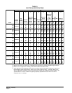
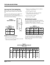
REFRIGERANT CHARGE
The correct system R-22 charge is shown on the unit
rating plate. Optimum unit performance will occur with
a refrigerant charge resulting in a suction line
temperature (6” from compressor) as shown in Table 6.
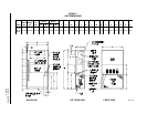
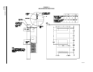
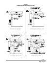
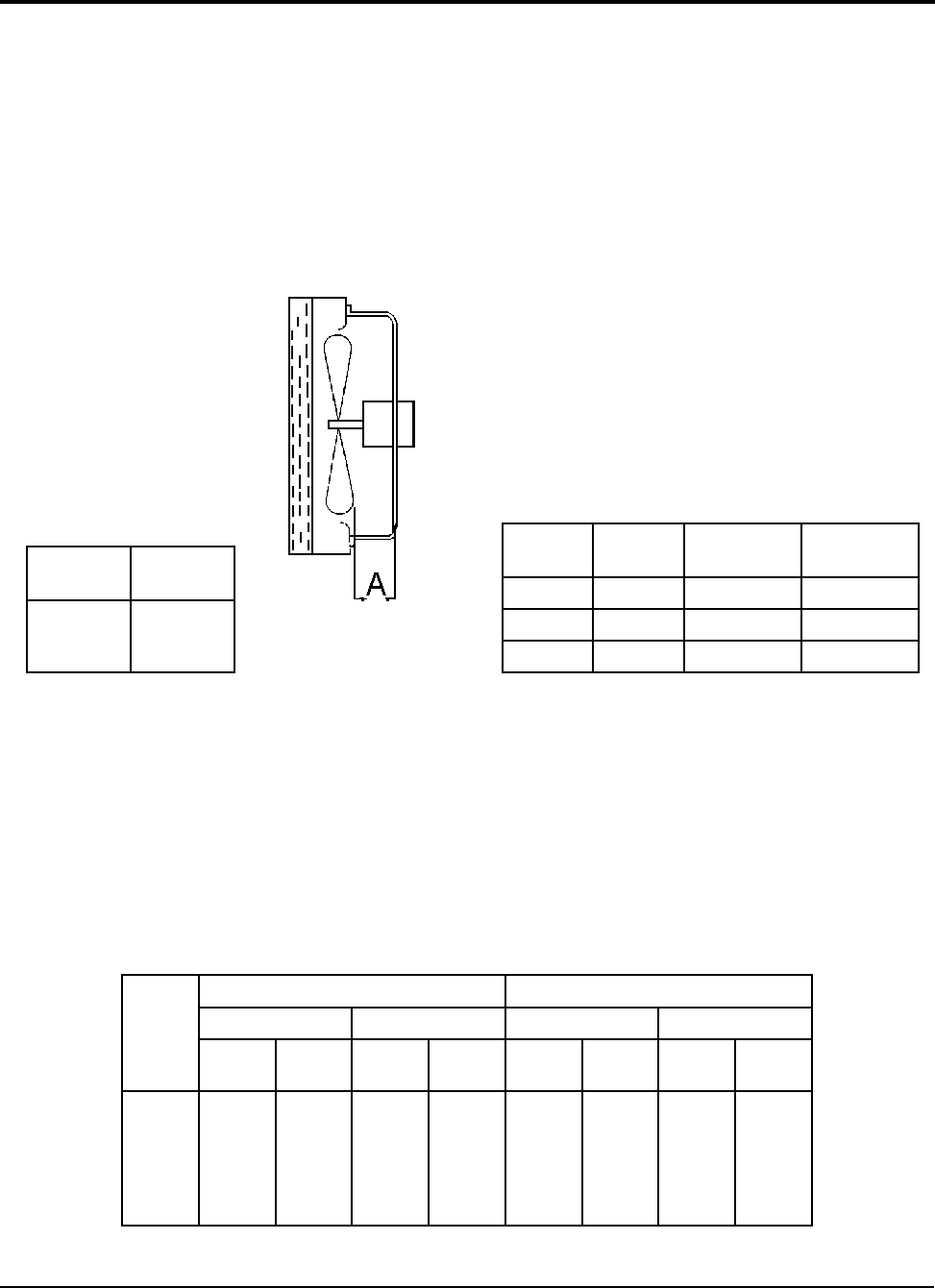
FIGURE 9
FAN BLADE SETTING
TABLE 5
FAN BLADE SETTING
DIMENSION
ledoM
noisnemiD
A
324LW
484LW
206LW
57.1
TABLE 6
REFRIGERANT CHARGE
ledoM
detaR
wolfriA
DO59
erutarepmeT
DO28
erutarepmeT
324LW004145-2566-46
484LW055165-4576-56
206LW007155-3526-06
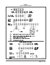
TABLE 7
INDOOR BLOWER PERFORMANCE
CFM
@
230V
.P.S.E
HnI
2
0
484LW,324LW206LW
V032woLV032hgiHV032woLV032hgiH
lioCyrD
teW
lioC
lioCyrD
teW
lioC
lioCyrD
teW
lioC
lioCyrD
teW
lioC
0.
1.
2.
3.
4.
5.
0561
0551
0541
0531
0031
---
0061
0051
0041
0031
5711
---
5881
0771
5361
0051
0731
0521
0081
5661
0451
0041
5821
0511
0061
5251
---
---
---
---
0541
5731
---
---
---
---
0022
0012
0002
5781
5771
0561
0002
0091
0081
0071
0061
5741
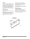
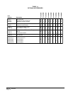
FAN BLADE SETTING DIMENSIONS
Shown in Figure 10 is the correct fan blade setting
dimension for proper air delivery across the outdoor
coil.
Any service work requiring removal or adjustment in
the fan and/or motor area will require that the
dimensions below be checked and blade adjusted in or
out on the motor shaft accordingly.