


Manual 2100-399
Page 15
now in operation. The second option has no "Auto"
changeover position, but instead energizes the reversing
valve solenoid constantly whenever the system switch
on subbase is placed in "Heat" position, the "B"
terminal being constantly energized from R. A
Thermostat demand for heat completes r-Y circuit,
pulling in compressor contactor starting compressor and
outdoor motor. R-G also make starting indoor blower
motor.
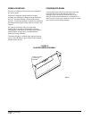
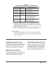
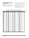
PRESSURE SERVICE PORTS
High and low pressure service ports are installed on all
units so that the system operating pressures can be
observed. Pressure tables can be found later in the
manual covering all models on both cooling and heating
cycles. It is imperative to match the correct pressure
curve to the unit by model number.
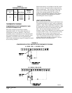
DEFROST CYCLE
The defrost cycle is controlled by temperature and time
on the solid state heat pump control.
When the outdoor temperature is in the lower 40° F
temperature range or colder, the outdoor coil
temperature is 32° F or below. This coil temperature is
sensed by the coil sensor mounted near the bottom of
the outdoor coil. Once coil temperature reaches 30° F
or below, the coil sends a signal to the control logic of
the heat pump control and the defrost timer will start.
After 60 (90 or 30) minutes at 30° F or below, the heat
pump control will place the system in the defrost mode.
During the defrost mode, the refrigerant cycle switches
back to the cooling cycle, the outdoor motor stops,
electric heaters are energized, and hot gas passing
through the outdoor coil melts any accumulated frost.
When the temperature rises to approximately 57° F, the
coil sensor will send a signal to the heat pump control
which will return the system to heating operations
automatically.
If some abnormal or temporary conditions such as a
high wind caused the heat pump to have a prolonged
defrost cycle, the heat pump control will restore the
system to heating operating automatically after 10
minutes.
There is a cycle SPEEDUP jumper on the control. This
can be used to reduce the time between defrost cycle
operation without waiting for time to elapse.
Use a small screwdriver or other metallic object, or
another 1/4 inch QC to short between the SPEEDUP
terminals to accelerate the HPC timer and initiate
defrost. Be careful not to touch any other terminals
with the instrument used to short the SPEEDUP
terminals. It may take up to 10 seconds with the
SPEEDUP terminals shorted for the speedup to be
completed and the defrost cycle to start.
SEQUENCE OF OPERATION
COOLING –
Circuit R-Y makes at thermostat pulling in
compressor contactor, starting the compressor and
outdoor motor. The G (indoor motor) circuit is
automatically completed on any call for cooling
operation or can be energized by manual fan switch on
subbase for constant air circulation.
HEATING –
A 24V solenoid coil on reversing valve
controls heating cycle operation. Two thermostat
options, one allowing "Auto" changeover from cycle to
cycle and the other constantly energizing solenoid coil
during heating season, and thus eliminating pressure
equalization noise except during defrost, are to be used.
On "Auto" option a circuit is completed from R-W1 and
R-Y on each heating "on" cycle, energizing reversing
valve solenoid and pulling in compressor contactor
starting compressor and outdoor motor. R-G also make
starting indoor blower motor. Heat pump heating cycle
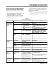
2. Switching to heating cycle at 75° F or higher outside
temperature may cause a nuisance trip of the remote
reset high pressure switch. Turn thermostat off, then
on to reset the high pressure switch.
3. The heat pump wall thermostats perform multiple
functions. Be sure that all function switches are
correctly set for the desired operating mode before
trying to diagnose any reported service problems.
4. Check all power fuses or circuit breakers to be sure
they are the correct rating.
5. Periodic cleaning of the outdoor coil to permit full and
unrestricted airflow circulation is essential.
SERVICE HINTS
1. Caution homeowner to maintain clean air filters at all
times. Also, not to needlessly close off supply and
return air registers. This reduces air flow through the
system, which shortens equipment service life as
well as increasing operating costs.
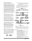
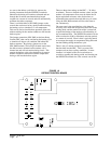
PHASE MONITOR
All units with three phase compressors are equipped
with a 3 phase line monitor to prevent compressor
damage due to phase reversal.
The phase monitor in this unit is equipped with two
LEDs. If the Y signal is present at the phase monitor
and phases are correct, the green LED will light. If
phases are reversed, the red fault LED will be lit and
compressor operation is inhibited.
If a fault condition occurs, reverse two of the supply
leads to the unit. Do not reverse any of the unit factory
wires as damage may occur.