Manual 2100-425
Page 9
NOTE: The voltage should be measured at the field
power connection point in the unit and while
the unit is operating at full load (maximum
amperage operating condition).
Five (5) wires should be run from thermostat subbase
to the 24V terminal board in the unit. A five
conductor, 18 gauge copper, color-coded thermostat
cable is recommended. The connection points are
shown in Figure 8.
WIRING — LOW VOLTAGE WIRING
230/208V, 1 phase and 3 phase equipment dual
primary voltage transformers. All equipment leaves
the factory wired on 240V tap. For 208V operation,
reconnect from 240V to 208V tap. The acceptable
operating voltage range for the 240 and 208V taps are
shown in Table 4 below.
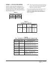
TABLE 4
OPERATING VOLTAGE RANGE
PATEGNAR
V042612-352
V802781-022
TABLE 5
THERMOSTAT WIRE SIZE
remrofsnarT
AVALFeguaGeriW
mumixaM
ecnatsiD
teeFnI
553.2
eguag02
eguag81
eguag61
eguag41
eguag21
54
06
001
061
052
TABLE 6
WALL THERMOSTAT AND SUBBASE COMBINATIONS
tatsomrehTesabbuSserutaeFetanimoderP
200-3048
1113F78T
300-4048
0221A935Q
loocegats1,taehegats1
no-otua:naFlooc-ffo-taeh:metsyS
140-3048
C4308T
---loocegats1,taehegats1
no-otua:naFlooc-ffo-taeh:metsyS
910-3048
0671C478T
210-4048
1001A476Q
taehegats2,loocegats1
no-otua:naFlooc-otua-taeh:metsyS
120-3048
4391D478T
210-4048
1001A476Q
taehegats2,loocegats2
no-otua:naFlooc-otua-taeh:metsyS
940-3048
083-39F1
---taehegats2,loocegats2
gnimmargorpyad7cinortcelE
340-3048
002-MC
---
loocegats1,taehegats1
no-otua:naFlooc-ffo-taeh:metsyS


