


Manual 2100-511F
Page 17 of 27
SEQUENCE OF OPERATION
COOLING – Circuit R-Y makes at thermostat pulling in
compressor contactor, starting the compressor and outdoor
motor. The G (indoor motor) circuit is automatically completed
on any call for cooling operation or can be energized by manual
fan switch on subbase for constant air circulation.
HEATING – A 24V solenoid coil on reversing valve controls
heating cycle operation. Two thermostat options, one allowing
“Auto” changeover from cycle to cycle and the other constantly
energizing solenoid coil during heating season, and thus
eliminating pressure equalization noise except during defrost,
are to be used. On “Auto” option a circuit is completed from R-
W1 and R-Y on each heating “on” cycle, energizing reversing
valve solenoid and pulling in compressor contactor starting
compressor and outdoor motor. R-G also make starting indoor
blower motor. Heat pump heating cycle now in operation. The
second option has no “Auto” changeover position, but instead
energizes the reversing valve solenoid constantly whenever the
system switch on subbase is placed in “Heat” position, the “B”
terminal being constantly energized from R. A Thermostat
demand for heat completes R-Y circuit, pulling in compressor
contactor starting compressor and outdoor motor. R-G also
make starting indoor blower motor.
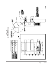
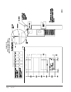
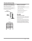
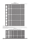
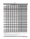
PRESSURE SERVICE PORTS
High and low pressure service ports are installed on all units
so that the system operating pressures can be observed.
Pressure tables can be found later in the manual covering all
models. It is imperative to match the correct pressure table
to the unit by model number. See Tables 3A & 3B.
DEFROST CYCLE
The defrost cycle is controlled by temperature and time on
the solid state heat pump control.
When the outdoor temperature is in the lower 40°F
temperature range or colder, the outdoor coil temperature is
32°F or below. This coil temperature is sensed by the coil
temperature sensor mounted near the bottom of the outdoor
coil. Once coil temperature reaches 30°F or below, the coil
temperature sensor sends a signal to the control logic of the
heat pump control and the defrost timer will start
accumulating run time.
After 30, 60 or 90 minutes of heat pump operation at 30°F or
below, the heat pump control will place the system in the
defrost mode.
During the defrost mode, the refrigerant cycle switches back
to the cooling cycle, the outdoor motor stops, electric heaters
are energized, and hot gas passing through the outdoor coil
melts any accumulated frost. When the temperature rises to
approximately 57°F, the coil temperature sensor will send a
signal to the heat pump control which will return the system
to heating operations automatically.
If some abnormal or temporary condition such as a high
wind causes the heat pump to have a prolonged defrost
cycle, the heat pump control will restore the system to
heating operation automatically after 8 minutes.
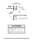
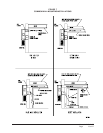
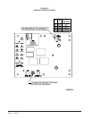
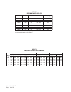
The heat pump defrost control board has an option of 30, 60
or 90-minute setting. By default, this unit is shipped from
the factory with the defrost time on the 60 minute pin. If
circumstances require a change to another time, remove the
wire from the 60-minute terminal and reconnect to the
desired terminal. Refer to Figure 8.
There is a cycle speed up jumper on the control. This can be
used for testing purposes to reduce the time between defrost
cycle operation without waiting for time to elapse.
Use a small screwdriver or other metallic object, or another
¼ inch QC, to short between the SPEEDUP terminals to
accelerate the HPC timer and initiate defrost.
Be careful not to touch any other terminals with the
instrument used to short the SPEEDUP terminals. It may take
up to 10 seconds with the SPEEDUP terminals shorted for the
speedup to be completed and the defrost cycle to start.
As soon as the defrost cycle kicks in remove the shorting
instrument from the SPEEDUP terminals. Otherwise the
timing will remain accelerated and run through the 1-minute
minimum defrost length sequence in a matter of seconds and
will automatically terminate the defrost sequence.
There is an initiate defrost jumper (sen jump) on the control
that can be used at any outdoor ambient during the heating
cycle to simulate a 0° coil temperature.
This can be used to check defrost operation of the unit without
waiting for the outdoor ambient to fall into the defrost region.
By placing a jumper across the SEN JMP terminals (a
¼ inch QC terminal works best) the defrost sensor mounted
on the outdoor coil is shunted out & will activate the timing
circuit. This permits the defrost cycle to be checked out in
warmer weather conditions without the outdoor temperature
having to fall into the defrost region.
In order to terminate the defrost test the SEN JMP jumper
must be removed. If left in place too long, the compressor
could stop due to the high pressure control opening because
of high pressure condition created by operating in the
cooling mode with outdoor fan off. Pressure will rise fairly
fast as there is likely no actual frost on the outdoor coil in
this artificial test condition.
There is also a 5-minute compressor time delay function built
into the HPC. This is to protect the compressor from short
cycling conditions. The board’s LED will have a fast blink rate
when in the compressor time delay. In some instances, it is
helpful to the service technician to override or speed up this
timing period, and shorting out the SPEEDUP terminals for a
few seconds can do this.
Low Pressure Switch Bypass Operation - The control has a
selectable (SW1) low pressure switch bypass set up to ignore
the low pressure switch input during the first (30, 60, 120 or 180
seconds) of “Y” operation.
After this period expires, the control will then monitor the low
pressure switch input normally to make sure that the switch is
closed during “Y” operation.
High Pressure Switch Operation - The control has a built-in
lockout system that allows the unit to have the high pressure
switch trip up to two times in one hour and only encounter a
“soft” lockout. A “soft” lockout shuts the compressor off and
waits for the pressure switch to reset, which at that point then
allows the compressor to be restarted as long as the 5-minute
short cycle timer has run out. If the high pressure switch trips a
third time within one hour, the unit is in “hard” lockout indicating
something is certainly wrong and it will not restart itself.