


Manual 2100-511
Page 21 of 27
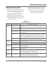
TROUBLESHOOTING
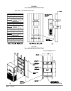
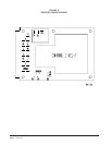
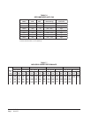
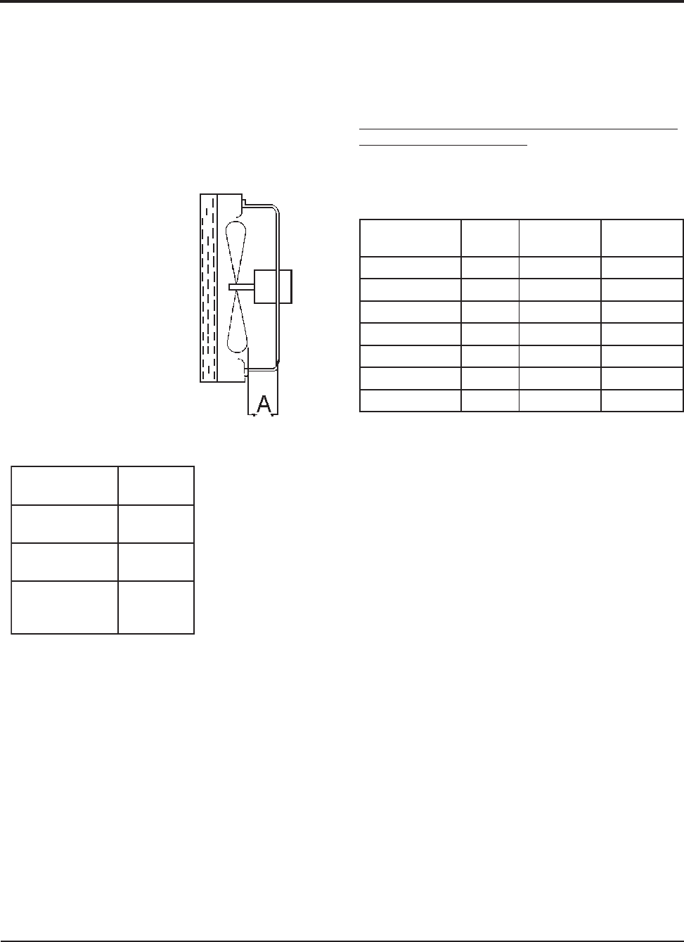
FIGURE 9
FAN BLADE SETTING
MIS-1724
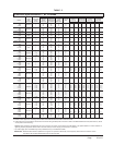
TABLE 2
FAN BLADE DIMENSION
REMOVAL OF FAN SHROUD
1. Disconnect all power to the unit.
2. Remove the screws holding both grilles, one on each
side of unit, and remove grilles.
3. Remove screws holding fan shroud to condenser and
bottom. Nine (9) screws.
4. Unwire condenser fan motor.
5. Slide complete motor, fan blade, and shroud
assembly out the left side of the unit.
6. Service motor/fan as needed.
7. Reverse steps to reinstall.
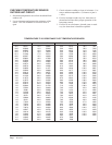
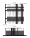
REFRIGERANT CHARGE
The correct system R-410A charge is shown on the unit
rating plate. Optimum unit performance will occur with
a refrigerant charge resulting in a suction line
temperature (6" from compressor) as shown in Table 3.
If charge quantity is in doubt, reclaim unit and recharge
to factory nameplate quantity.
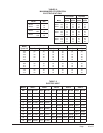
The suction line temperatures in Table 3 above are
based upon 80°F dry bulb / 67°F wet bulb (50% R.H.)
temperature and rated airflow across the evaporator
during cooling cycle.
TABLE 3
REFRIGERANT CHARGE
ledoM
detaR
wolfriA
DOF°59
erutarepmeT
DOF°28
erutarepmeT
1H81W00616-7566-26
1H42W00826-8536-85
1H03W000126-8566-26
1H63W001126-8516-75
1H24W004156-1696-56
1H84W055146-0676-36
1H06W056146-0696-56
ledoM
noisnemiD
A
1H81W
1H42W
"00.1
1H03W
1H63W
"52.1
1H24W
1H84W
1H06W
"57.1
FAN BLADE SETTING DIMENSIONS
Shown in Figure 9 is the correct fan blade setting for
proper air delivery across the outdoor coil. Refer to
Table 2 for unit specific dimension.
Any service work requiring removal or adjustment in
the fan and/or motor area will require that the
dimensions below be checked and blade adjusted in or
out on the motor shaft accordingly.