


Manual 2100-532B
Page 19 of 46
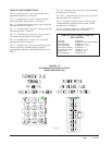
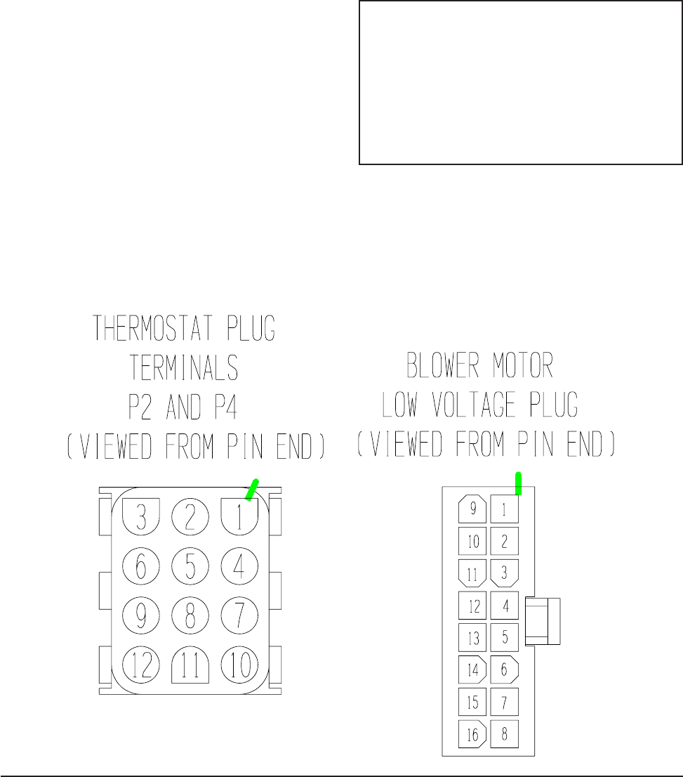
LOW VOLTAGE CONNECTIONS
The “R” terminal is the 24 VAC hot terminal and is
supplied through Pin #10 of Plug P2.
The “C” terminal is the 24 VAC common/grounded
terminal and feeds through Pin #11 of Plug P2.
The “G” terminal is the indoor blower input signal and
feeds through Pin #6 of Plug P2.
The “Y1” terminal is the compressor starting signal and
feeds through Pin #7 of Plug P2.
The “Y2” terminal is the compressor staging solenoid
signal and feeds through Pin #4 of Plug P2.
The “O” terminal is the reversing valve signal and
feeds through Pin #8 of Plug P2.
The “A” terminal is the ventilation demand signal and
outputs a signal for ventilation during occupied
programming conditions, and feeds through Pin #5 of
Plug P2.
The “W2” terminal is the electric heat signal and feeds
through Pin #9 of Plug P2.
The “W1/E” terminal is the emergency heat signal and
feeds through Pin #3 of Plug P2.
The “L” terminal is used as an input terminal when a
CS2000 infrared occupancy device is used. It feeds
through Pin #12 of Plug P2.
The “D” terminal is used only of dehumidification
models and feeds through Pin #1 of Plug P2.
LOW VOLTAGE CONNECTIONS FOR
DDC CONTROL
Fan Only Energize G
Ventilation Energize G, A (any mode of operation)
Part Load Cooling Energize G, Y1, O
Full Load Cooling Energize G, Y1, Y2, O
Part Load HP Heating Energize G, Y1
Full Load HP Heating Energize G, Y1, Y2
Electric Heat Energize G, W2
Dehumidification Energize G, D, O
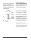
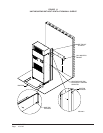
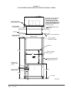
FIGURE 13
BLOWER MOTOR LOW VOLTAGE
WIRE HARNESS PLUG
MIS-1285