


Manual 2100-522B
Page 21 of 38
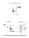
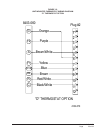
LOW VOLTAGE CONNECTIONS
FOR DDC CONTROL
Fan Only Energize G
Cooling Mode Energize Y1, G
1st Stage Heating Energize G, W1
2nd State Heating Energize G, W2
(if employed)
Ventilation Energize G, F
GENERAL
This unit is equipped with a variable speed ECM motor.
The motor is designed to maintain rated airflow up to
the maximum static allowed. It is important that the
blower motor plugs are not plugged in or unplugged
while the power is on. Failure to remove power prior
to unplugging or plugging in the motor could result in
motor failure.
CAUTION
Do not plug in or unplug blower motor
connectors while the power is on.
Failure to do so may result in motor failure.
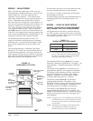
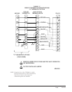
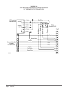
LOW VOLTAGE CONNECTIONS
These units use a grounded 24 volt AC low voltage
circuit.
The “R” terminal is the hot terminal and the “C”
terminal is grounded.
“G” terminal or pin 6 of P2 is the fan input. If the
climate control option is abandoned and connections are
made directly to P2 pin 6 of P2 must be energized for
proper operation.
“Y1” terminal or pin 7 of P2 is the compressor input.
“W1” terminal or pin 8 of P2 is the fist stage heat.
“R” terminal or pin 10 of P2 is 24 VAC hot.
“C” terminal or pin 11 of P2 is 24 VAC grounded.
“L” terminal or pin 12 of P2 is compressor lockout
output. This terminal is activated on a high or low
pressure trip by the electronic heat pump control. This
is a 24 VAC output.
“W2” terminal or pin 9 of P2 is second stage heat (if
equipped). If the unit is equipped with an optional hot
water coil plenum box or electric heat these will be
energized by this terminal.
“F” terminal of pin 5 of P2 is the ventilation input.
This terminal energizes any factory installed ventilation
option.
NOTE: For total and proper control using DDC, a total
of 5 controlled outputs are required (4 if no
ventilation system is installed).