


Manual 2100-522B
Page 2 of 38
CONTENTS
Figures
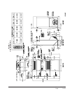
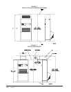
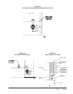
Figure 1 Unit Dimensions .......................................... 7
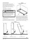
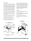
Figure 2 Air Seal Under Unit...................................... 8
Figure 3 Removal of Unit From Skid ......................... 8
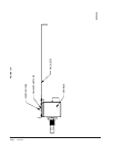
Figure 4 Unit on Appliance Cart for Moving ...............9
Figure 5 Installation With Free Blow Plenum .......... 10
Figure 6 Ducted Application..................................... 10
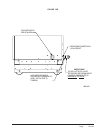
Figure 7 Supply Duct Connections .......................... 11
Figure 8 Filter Location ............................................ 11
Figure 9 Optional Side Drain ................................... 13
Figure 10 Standard Rear Drain.................................. 13
Figure 11 Rear Drain (Top View) ............................... 13
Figure 12A
Optional Rear Drain Kit ............................. 14
Figure 12B
Optional Rear Drain Kit ............................. 15
Figure 12C
Optional Rear Drain Kit ............................. 16
Figure 12D
Optional Rear Drain Kit ............................. 17
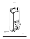
Figure 13A
Unit Mounting ............................................ 18
Figure 13B
Unit Mounting ............................................ 18
Figure 14 Removing Locking Screws from Wheels... 19
Figure 15 Component Location ................................. 20
Figure 16 Thermostat Plug Terminals........................ 22
Figure 17 Thermostat Wiring Diagram "X" Option.... 23
Figure 18 Thermostat Wiring Diagram "A" Option.... 24
Figure 19 Thermostat Wiring Diagram "D" Option ... 25
Figure 20 Thermostat Wiring Diagram "H" Option ... 26
Figure 21 Fresh Air Damper Removal ....................... 32
Figure 22 QERV Removal ......................................... 33
Figure 23 CO
2
Controller ........................................... 34
Figure 24 Control Disassembly ................................. 36
Figure 25 Winding Test ..............................................36
Figure 26 Drip Loop ................................................... 36
Figure 27 Fan Blade Setting ...................................... 37
Tables
Table 1 Factory Built-In Electric Heat Table .............. 5
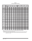
Table 2 Electrical Specifications ................................ 6
Table 3 Operating Voltage Range ........................... 20
Table 4 Wall Thermostats ........................................ 22
Table 5 Fan Blade Dimensions ............................... 37
Table 6 Indoor Blower Performance ........................ 37
Table 7 Cooling Pressure ........................................ 38
Getting Other Information and Publications
For more information, contact these publishers:.......... 3
Q-T
EC General Information
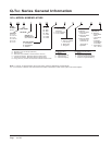
Q-TEC Model Nomenclature ......................................... 4
Shipping Damage......................................................... 8
Unit Removal From Skid .............................................. 8
Handling Unit After Removal From Skid....................... 9
General......................................................................... 9
Minimum Installation Height ......................................... 9
Duct Work .................................................................. 11
Filters.......................................................................... 11
Fresh Air Intake .......................................................... 12
Service Light............................................................... 12
Condensate Drain ...................................................... 12
Optional Rear Drain Kit .............................................. 12
Separate Evaporator Drain Connection ..................... 12
Installation Instructions
Mounting the Unit ....................................................... 19
Wiring — Main Power................................................. 20
Wiring — Low Voltage Wiring..................................... 20
Low Voltage Connections........................................... 21
General....................................................................... 21
Start Up
R-410A Refrgerant ......................................................... 27
Topping Off System Charge ........................................... 27
Safety Practices ............................................................. 27
Description of Standard Equipment ............................... 28
Optional CFM (Q36A1, Q42A1, Q48A1 & Q60A1 Only) 28
Important Installer Note.................................................. 28
Phase Monitor ................................................................ 28
Three Phase Scroll Compressor Start Up
Information ....................................................... 28 & 29
Compressor Control Module .......................................... 29
Adjustments ................................................................... 29
Service Hints ......................................................... 29 & 30
Mist Eliminator Service .................................................. 30
Vent Options ......................................................... 30 & 31
Sequence of Operation .................................................. 34
Optional Climate Controls Sequence
of Operation .............................................................. 34
Pressure Service Ports .................................................. 34
Troubleshooting
Troubleshooting GE ECM™ Blower Motors............. 35-36
Fan Blade Setting Dimensions ...................................... 37
Refrigerant Charge ........................................................ 37
Pressure Chart ............................................................... 38