


Manual 2100-522B
Page 37 of 38
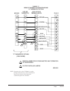
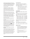
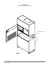
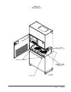
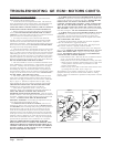
FAN BLADE SETTING DIMENSIONS
Any service work requiring removal or adjustment in
the fan and/or motor area will require that the
dimensions in Table 5 be checked and blade adjusted in
or out of the motor shaft accordingly.
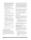
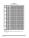
1 Maximum ESP (inches WC) shown is with 1" thick disposable filter (reduced by .2 for 2" filter).
2 Rated CFM for ducted applications – required for maximum performance rating. To obtain full CFM on models Q36A1, Q42A1, Q48A1 and
Q60A1 connect the pink jumper wire (provided) to terminal #G2 and #Y on the low voltage terminal block located in the circuit breaker box.
3 Optional CFM – the unit is shipped from the factory set to operate at the optional CFM level shown. This provides lower operating sound
levels for non-ducted, free discharge applications. This reduces system capacity performance by approximately 2% at the same energy
efficiency.
4 Continuous fan CFM is the total air being circulated during continuous fan mode.
5 Model Q24A1 – when operating on 2nd stage heating the indoor air will increase to 1000 CFM.
R-410A
REFRIGERANT CHARGE
This unit was charged at the factory with the quantity of
refrigerant listed on the serial plate. AHRI capacity and
efficiency ratings were determined by testing with this
refrigerant charge quantity.
The following pressure tables show nominal pressures
for the units. Since many installation specific situations
can affect the pressure readings, this information should
only be used by certified technicians as a guide for
evaluating proper system performance. They shall not
be used to adjust charge. If charge is in doubt, reclaim,
evacuate and recharge the unit to the serial plate charge.
FIGURE 27
FAN BLADE SETTING
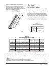
TABLE 5
FAN BLADE DIMENSIONS
LEDOM
ANOISNEMID
)SEHCNI(
llA
1A**Q
sledoM
057.
NOTE: These units are equipped with a variable speed (ECM) indoor motor that automatically adjust itself to
maintain approximately the same rate of indoor airflow in both heating and cooling, dry and wet coil
conditions and at both 230/208 or 460 volts.
TABLE 6
INDOOR BLOWER PERFORMANCE
ledoM
PSEdetaR
1
PSE.xaM
2
MFCdetaR
3
lanoitpO
MFC
4
suounitnoC
MFC
@MFC
xaM
PSE.
1A42Q
5
01.5.0008008007
1A03Q51.8.000010001019
1A63Q51.8.00021000100015711
1A24Q51.8.00021000100015711
1A84Q51.8.00041001100115711
1A06Q02.5.00551052105210041